
Over the last few days I had the opportunity to borrow a 40m Transmitting Magnetic Loop Antenna with a big thanks from Steve – VK5SFA for the loan of his 40m loop so I could conduct some comparisons.
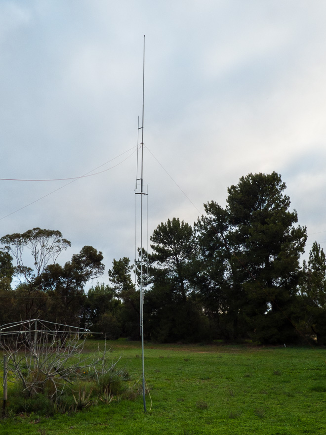
We were at the shack in PF95wu where I have the GAP Challenger Vertical and where I could put up my portable 40m Inverted V antenna.
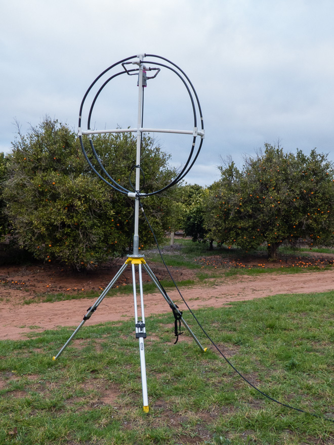
The loop is physically quite small at only about 1.6m in diameter – and as you can see it was mounted on a tripod with the bottom only 1.8m off the ground, and as far away as my coax would allow from the shack – which was about 10 or 12 Metres.
The Gap Challenger, which has been put to use as the primary RX antenna for the KiwiSDR – was one of the comparison antenna’s used over the few days.
For the TX experiments I used the KX3 and HR-50 Amp and was transmitting at between 40 and 55 Watts of power.
Observations – the Loop
The bandwidth of the loop was quite pronounced – tune the loop, tune the RX across the band and it was pretty obvious – about 40khz wide.
TX – well, it was nowhere near 40Khz wide – more like about 12 or 13khz 1.5:1 VSWR bandwidth.
The first night, we had a bit of rain earlier and the ground was a little damp. We found it impossible to actually tune the loop – best we could get was about 4:1 VSWR on TX. The next night it was much better!
Tuning – well touchy is an understatement! The tuning is manually done via an insulated rod – and 1/4 of a turn was like 40khz! It was a case of tuning for maximum RX noise, then some careful fine-tweaking to get it there.
RX Bandwidth
The Loop was tuned to 7.140 and plugged into the SDR
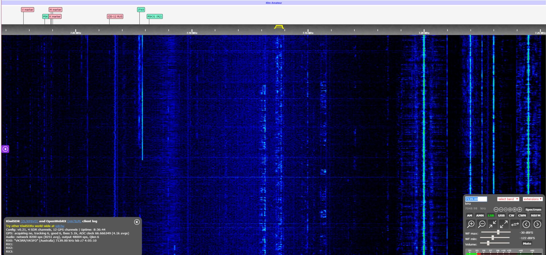
Without changing any settings on the SDR, the Vertical was plugged back in.
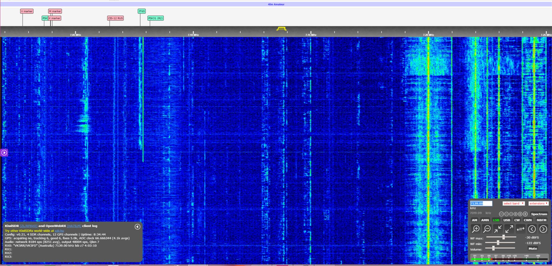
IT is pretty obvious as to the RX bandwidth and how sharp it drops off away from the centre frequency.
Click on both Images to see full sized.
Usage
I made use of the Loop to talk during the day – local, single-hop contacts (VK2, VK3, VK4) – and when 40m is open, it is open – 59 contacts – no real difference between any antenna. DX – I did have a couple of contacts to the West-Coast US using the Loop – and got respectable reports back based on my 50W!
The Loop has 2 large lobes, and quite a deep, but fairly narrow null on each side. The null is about 50-60 degrees and 2 S-points – or probably around the 12db mark (give or take). We did have a little bit of local noise, and rotating the loop we observed the noise drop right off to S1-2 when nulling the noise.
Side by side, with the Vertical – RX was on par, and TX was much better – just because there is a slight directivity associated with the loop .
Side by side with the Inverted V – well this was much more interesting – The Inverted V was only 8m high with each end about 2m off the ground.
The Inverted V was 2-3 S-points noisier than the Loop, but also 1 S-point stronger on the signals. With an S6 noise and S9 Signal for the VK contacts, versus’s the loop, with an S3-4 noise and an S8 signal.
It clearly had at least 10db better signal to noise versus’s the Inverted V – and well, hands down beat the Vertical on TX!
The far stations reported slightly stronger signals on the Inverted V, but I don’t hold much faith in that as there was heavy QSB – I would call it a tie.
Conclusions
I would conclude that it is about on par with a dipole in typical performance – but has a considerably smaller footprint! I was actually not expecting that the performance to be as close to the Dipole/Inverted V as it actually was – remarkable considering that you only need a very small space to have the equivalent of a rotatable dipole!
For the Amateur who is space-challenged or has a lot of noise, then yes, a loop is certainly worth considering for the low bands.
As we have the Loop for a couple more days, we will set it up in a typical urban lot – where we simply cannot use 40m as it is always S9+ noise and make some observations as to how effective it is in a much noisier environment.
Thanks for sharing your experiment.
Its good to see real life situation and the comparison is very interesting.
For SDR receive the bandwidth is a bit of an issue as you can’t take the advantage of wide receiver spectrum.
Adrian, The example of putting it on the SDR was to show just how narrow the B/W of the loop is- and if you look at the image – where it goes from blue to black is approx 40db – so it is very tight – and obviously aids to the selectivity quite well.
Loop is certainly no good for a wideband RX situation
Thanks Bob,
Very interesting results. Will be interested in your further comparisons.
Great description of your testing Bob! I have used the antenna whilst out portable in the field and concur with your results.
Great NVIS performance with the ability to work international DX as well.
We will have to get to the bottom of why the antenna is so sensitive to moisture. Might be the temporary waterproofing around the variable vacuum capacitor not doing its job?
The 160/80 metre version at my QTH does not suffer poor return loss when it is raining or the ground being damp.
Thank you for sharing, Steve & it is interesting to make & review valid field comparisons.
It is what it is and does what it does & I will be interested to follow-up with a 6×4 trailer-mounted MF version for field days & other transportable operations – perhaps to inform an article in the sequel to “MF Down Under”.
Good stuff!!
de Doc/VK5BUG
Editor: “MF Down Under”
UPDATE : We returned the Loop to Steve today and identified what was causing such poor performance of the loop… It was all about the missing Common mode Choke on the feedline! We did not have it! This explains why when the ground was wet it wouldn’t tune – the wet ground with the coax running over it was literally eating all the RF!
Maybe we will be able to conduct these experiments again in the future and make sure we have the feedline chokes as well!
Lack of common choke means that your coax was part of the antenna. Therefore comparison with other antennas could not be repeated elswhere with different length of cable etc.
Thanks for the comments – and yes, that was noted in other comments. Whilst there was no choke to de-couple the feedline from the antenna, that observation was also made with the inability to tume when the soild conductivity was high (ie wet after the rain) – all other things considered, I was the 4th person to observe very similar results to what I have presented, It is simply a case where after I conducted the experiments I was informed of the results of other people – and this was done specifically so I would not have a bias as to the results. The only thing missing is a write-up of the findings of others who have used this antenna.