
One of the Radio Activites I have really enjoyed over the last few years is the Oceania DX Contest – where the world points their antenna’s to Oceania and we are the wanted stations.
I have chosen to enter a category of SingleOp All band (160-80-40-20-15-10) SSB QRP.
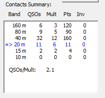
My first entry was in 2016, and it was basically on a bit of a whim, and I made a handful of contacts, submitted a log and to my surprise actually came 1-3-3 (Country-Continent-World) with a score of 2660 Yes, First in VK, 3rd in Oceania and 3rd in the world.
This motivated me somewhat to actually put in more of an effort for 2017, and in 2017, my score was 30% higher than the winning score from 2016. Fast forward a few month’s and my results were 1-2-2 with a score of 10,368. Yes I had achieved 1 aim of improving my score and this time moved up to 2nd in the world. The conditions in 2017 were nowhere near as good as the previous year either.
Fast forward to early August (2018) when the 2017 Results were published, and it prompted me again to see what I could do to again further improve my score.
It came down to the 1 thing that I could change – and that is to work really hard on Antenna’s – and that is what I did.
First off, I spent some to time to come to terms learning and understanding how to use 4nec2 to model antennas and started off with the basics – model a simple dipole (Inverted-V) antenna and use it as a baseline to validate that the model was about what I was seeing in the real world – and yeah, close enough to not get too hung up about things.
Secondly, I modeled the Antenna’s I had used for the 2017 OCDX and this alone was a real eye-opener – and actually really surprised me as to how much of a disadvantage I had put myself at!
My Antenna choices for 2017 were.
- Titan Challenger 80-10 Vertical
- End-fed “random” wire of about 57M long and 8M high with a couple of counterpoise wires
- inverted V on 40 (and also used on 15m)
- 20m 1/4 WL vertical with elevated feedpoint and radials
The Titan vertical is an awesome RX antenna – but pretty useless for TX – so was hardly used for TX. The Inverted V – yep NVIS only on 40M and the 20M Vertical was OK.
As I had done my base learning and modelling of the 40M inverted V, I knew the pattern is all up – so not a DX antenna at all, so I went ahead and modeled my longwire across the 3 bands I used it on.
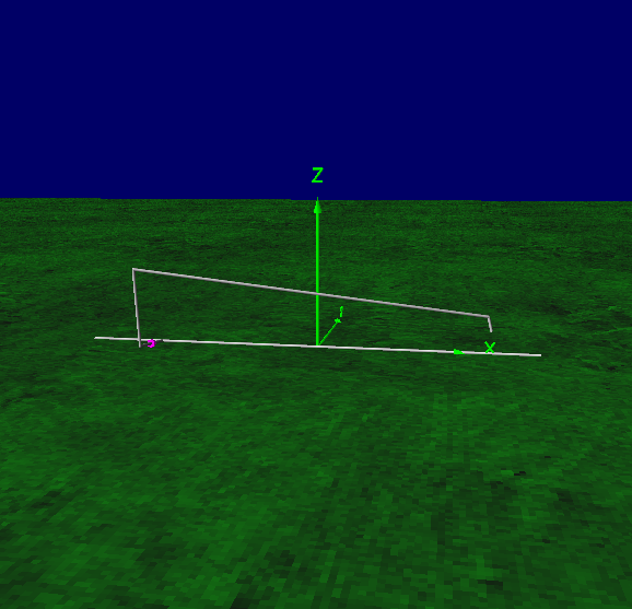
Once I had entered all the data, it was time to run some modelling across the 3 bands that I used this antenna on – and this is where things really sunk in!
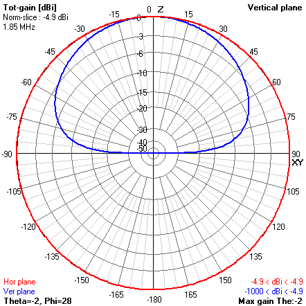
At first glance for a simple Antenna on 160M this looked OK, not all the signal was straight up, but then the I noticed the gain – Ouch – -4.9dBi – I was literally taking my 5W of RF and throwing most of it away and effectively using on about 1.5W!
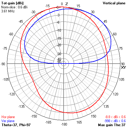
The 80M pattern was not really a lot better – Again, only 0.6dBi gain – and the main lobe was pointing in totally the wrong direction for for me to actually use! with the 90 being North, most of my power was being sent right into the Southern Ocean where there is literally Nobody!
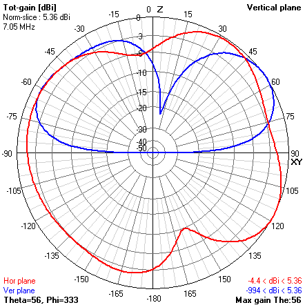
The 40M pattern again was not brilliant – whilst a slight gain of 5dBi when looking at the pattern, it was mostly in the wrong direction again! where I needed it – there was a nice deep null where I really needed a signal and probably why in hindsight that I relied on the 40M Inverted V for most of my 40M contacts.
The Challenge
Now, with an insight of how bad the antennas utilized actually were, I needed to look at modelling some better Antenna’s – and the beauty of modelling, is the try before build – which means fitting Antenna’s into the available space I had. the second Challenge was to do all this and actually build all the required antenna’s within a fairly short period.
40M – (my favourite band) – I wanted a decent Antenna on 40M as this is a band that I love operating on. Whilst the dream is a 4-Square array and yes, I’m fortunate enough to have (just) enough space for such an antenna, I didn’t have the time to build it – so off to the Internet and looking at what I might be able to do given all the restraints I had.
In the end I came up with a 2 Element Vertical Beam – that took me many iterations in 4nec2 to come up with something that met my objectives and was actually a reasonable match as well.
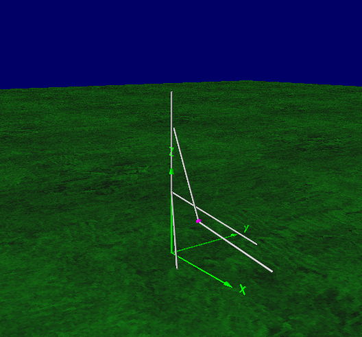
Now this does not look like a “conventional” beam, given the reflector is 3 segments and not the usual 2. and it is a very “odd” looking shape – but hey, this will become clearer as I explain a bit more.
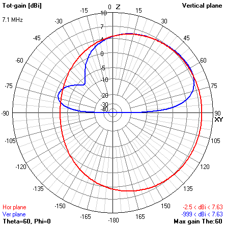
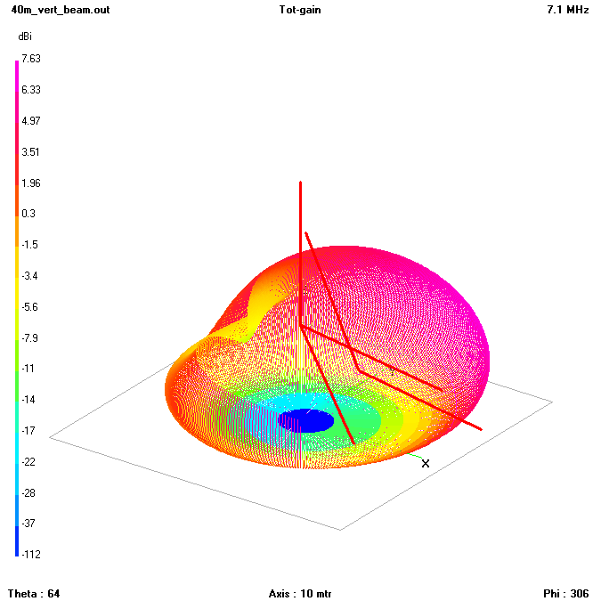
Notice anything nice about this radiation pattern – again 90deg on the circle is North.
Not only have I got a nice wide (about 200 degrees) beamwith, pointing in the desired direction (mostly)but there is nothing wasted out the back, and look at the vertical pattern is – an awesome DX Antenna. and with 7.6dBi gain, yet still enough for the up for the close NVIS/single hop contacts.
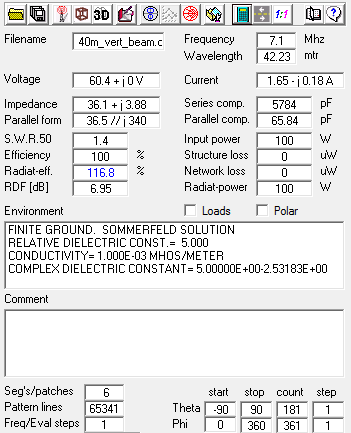
Not only did I get the desired pattern, it is a pretty darn good match!
Now the reason for the “odd configuration” Simple, the 12M squid pole supporting the reflector and the top of the driven element is mounted at 7 Metres high on top of a shed, and I needed to have the reflector split to go each side of the shed. Nothing more than adapting a design and working it into the environmental’s and space you have available.
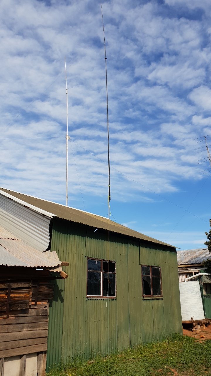
Make no mistakes, this is a BIG antenna – the top of the 12M Spiderbeam pole that is supporting the antenna is up at about 19M high and dwarfs the 2M antenna on the adjacent pole. the photo is taken lookup up along 1 of the reflector elements.
So this antenna was erected a couple of month’s ago and wow – does it perform! Very impressed with the results before the OCDX – and the real-world usage indicated that the modelling was in fact very close to the results.
The Low Bands
I spent a lot of time researching as to what sort of antenna’s I could use on the low bands that were going to be achievable in the 4 weeks I had left and eventually settled on a 160M Horizontal loop for a few reasons – mainly because after reading and modelling a lot of different options, this was the antenna I could use and it met (most of) my design objectives. It is also one of the few antenna’s that the relative performance is much better than a Dipole at low heights – as a 160M and 80M dipole at the 9M height i could achieve with this loop was no better than the random wire I used in 2017.
I did model a few that I would love to build that are in fact much better than a horizontal loop, but ran out of real estate to install it. Co-incidentally, it was also a very good option for being so close to the ground on the low bands.
The loop was modeled, then the model was re-worked once it was installed to reflect what was actually installed. I ended up feeding the loop with 300 ohm Ribbon cable, with a short Coax from Radio to a 1:4 balun. Whilst it is not a perfect match, the Tuner was easily able to achieve a decent match on both 160 and 80, and the analyzer gave me a good indication that It is in fact resonant where I needed it on these 2 bands.
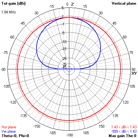
Now while this pattern might not seem like it is a big improvement over the 2017 one – it actually is a massive improvement. Yes, it is a lot of straight up, but it is 1.4dBi gain – or a 6db improvement over the previous year – and where every watt counts…
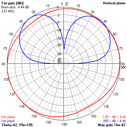
Again, at first glance, 80M doesn’t look to be brilliant, but then again – a big step up from the previous year with around a 3db improvement. The nothing straight up was not really a hindrance to how it performed and it was remarkably good.
The Higher Bands
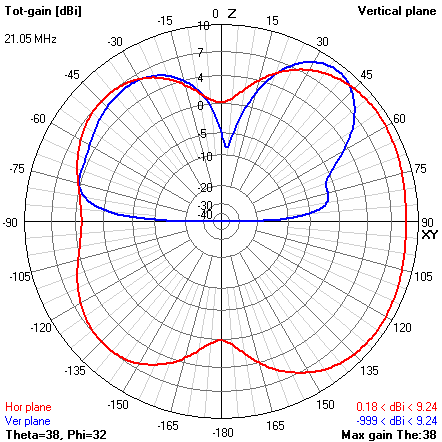
For 20M this year, I opted for a Full wavelength dipole with the 3/4 w/l leg pointed at around 120 Degrees. this antenna provides a broad “beam” with around 5db forward gain along the longer segment at reasonably low radiation angle and a bit of F/B. – Again, not the “perfect” antenna, but proved to be better than the previous year.
Given that 20M is literally the POWER band I was simply hoping to grab a handful of multipliers here and If I worked 10 I would be happy. I did miss out on a Short Path EU opening because I had the antenna fixed in a single direction and if I had anther antenna or been able to quickly re-orient this one may have picked up a few more contacts.
I used the 40M antenna on 15 as well – and yeah, some more effort needs to go into the modelling of the antenna to see if the 15M could be improved without degrading the primary band, or of course build a better 15M antenna – something for next year.
This year, the gap vertical was again used but mainly for RX, with exactly 2 contacts on it – 1 on 40M to VK7 where I am at a slight disadvantage on the Beam and 1 on 10M.
Honestly, I did not put much effort into the high bands (15 and 10) given the band conditions and unlikely chance of a decent opening on these bands.
The Results
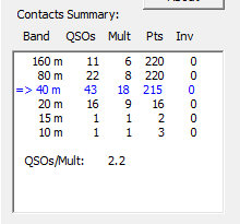
Well the proof of the modelling and antenna effort was well and truly rewarded.
This year, the conditions were nothing short of horrid yet I was able to nearly triple my score and my submitted score this year is 29,068
The bottom line is and, what I hope is the take-away after reading this post is Antenna’s matter – and if you take the time, model what you have you can (generally) work out how to do something better than what you may already have in place.
Final word – I enter QRP not because it is easy, but because it is hard!
VK5 is of course also at an added disadvantage – given that we are 1 hop further away than the other states – and over land and not water, further compounding the need to maximize our Antenna efforts.
I missed out on a heck of a lot of potential contacts because in am 20+ dB down with my power, but I had a blast actually doing what I did.
Update 12/10
I forgot to mention and now adding it in here.
One of the issues I had last year was my callsign – VK5FO – Whilst it has a certain charm and schoolyard smut factor, it was actually a problem during contests. I spent a fair bit of time, listening to the bands, listening to callsigns and then went and looked at available callsigns.
I applied for and was Granted VK5HC (Hotel Charlie, Henry Charlie, Honolulu California, or my favourite – welcome to the Hotel California) and yes, the callsign makes a difference when you are (I am) on the RX stations noise-floor). The callsign choice probably helped me actually complete 5 to 10% of the very difficult contacts.
A “contest callsign” that is phonetically easy is a worthwhile addition
Well done Bob, perseverance certainly pays off!
And a good read, thanks
Thanks Ben, Was a challenging and fun weekend of Radio.
Strewth! You certainly deserve a good result! I admire your spirit in running qrp, and your reasoning is spot on! Your explanation is quite comprehensive and will take a while to analyse. It is good that you had fun, but it sounds like a long wait for results 🙁
Also, thanks for the description of the contest. I had not realised its popularity. Is there much cw activity?
Well done, and keep enquiring and experimenting!
Adrian, 1st Full Weekend is the SSB/Phone section and the 2nd full weekend is the CW section. – check out the website – OCDX website
A good read Bob, M0MCX standardises at 5° elevation for his modelling to check gains 🙂
I’m not game at the moment to try modelling my home antennas, will have to learn 4nec one day I suppose.
Thanks Pete, My whole idea of modeling is comparative – what difference is there between 2 different Antenna’s – and remember, for this contest, for me more than 90% of my contacts were VK/ZL and close Pacific – so 1 or 2 hops – and the sub-45 deg gain is what I really needed, and not too much wasted straight up.
Bob,
Nice to see that thought and effort brings results – well done.
Thanks Chris – and a 2nd Thanks for the loan of the Balun until I build another one – without which the 160M Loop would not have been possible.
Well done Bob – fantastic effort in what was absolutely abysmal solar conditions particularly on the higher bands.
Thanks Grant… and not just the higher bands. 40 was not too flash either!
Great effort Bob, thanks for sharing your experience. Sorry I was not free to make contact with you, (45th wedding anniversary.)
Now for the wait for the results. Cheers, Ivan.
Top effort Bob and an entertaining read as always. No point spraying RF where there are more penguins than people!
Wow Bob that’s great work and a great article. I hope you have a good result, with the work you put in you deserve it.