Category Archives: Contesting

OCDX 2019

Well, a little late with this post, but better late than never!

The 2018 Results (finally) came in and as per my log submission and and checking all other online submissions, I did indeed come in at First place in 2018.

Onto this (last) year

During the period leading up to the 2019 Contest, I actually did little more than some minor (or not so minor) maintenance on various aspects of the Station and Antenna’s.  I had a few repairs to make, made a few (undocumented) discoveries that really improved the station.

First off – Repairs – The 160M horizontal loop suffered a break, and when I put it back together, I found that I was getting all sorts of interference in the shack.  With as little as 5W of RF on 160, the Computer was disconnecting from the Radio.   So job #1 was to investigate.

Like a lot of people , over the last year I had purchased a NanoVNA (every Ham needs one of these!) and ran a sweep over the Loop, only to find that for some strange reason it was nowhere near where it was last year!  I spent ages checking, trimming and tuning the antenna and managed to get it sorted out and back in tune on both 160 and 80M.  At this point, the RF in the shack was EVEN WORSE! and the PC connection was not usable to track bands for the logging software  now down to 1W!.  Given that this was the day of the OCDX, too bad, I had to live with manually setting the band in VKCL for logging.

I did in fact sort this out – and all it took was to actually install an Earth!  Yes, Guilty, like probably a LOT of Amateurs, I had managed to get away without having a dedicated Station Earth.   So a coupe of weeks after the OCDX, a standard 4 foot copper clad steal earth stake was banged into the dirt at a location where I could run a physically short earth wire to the TXCVR, and Voila, 100W on any band on the Horizontal loop and no Computer issues.   I do suspect that I may still have work to do to work out why the RF was starting to get into the shack and I actually suspect that I have not been careful enough with the ladderline from the look and keeping it far enough away from metal allowing it to become un-balanced and actually radiating – more work to do so I ensure that I am not just dumping RF to dirt rather than radiating.

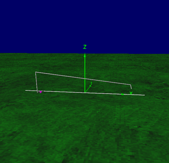
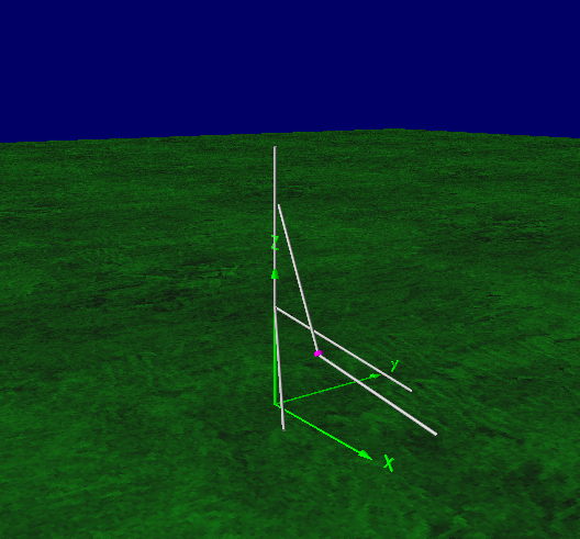
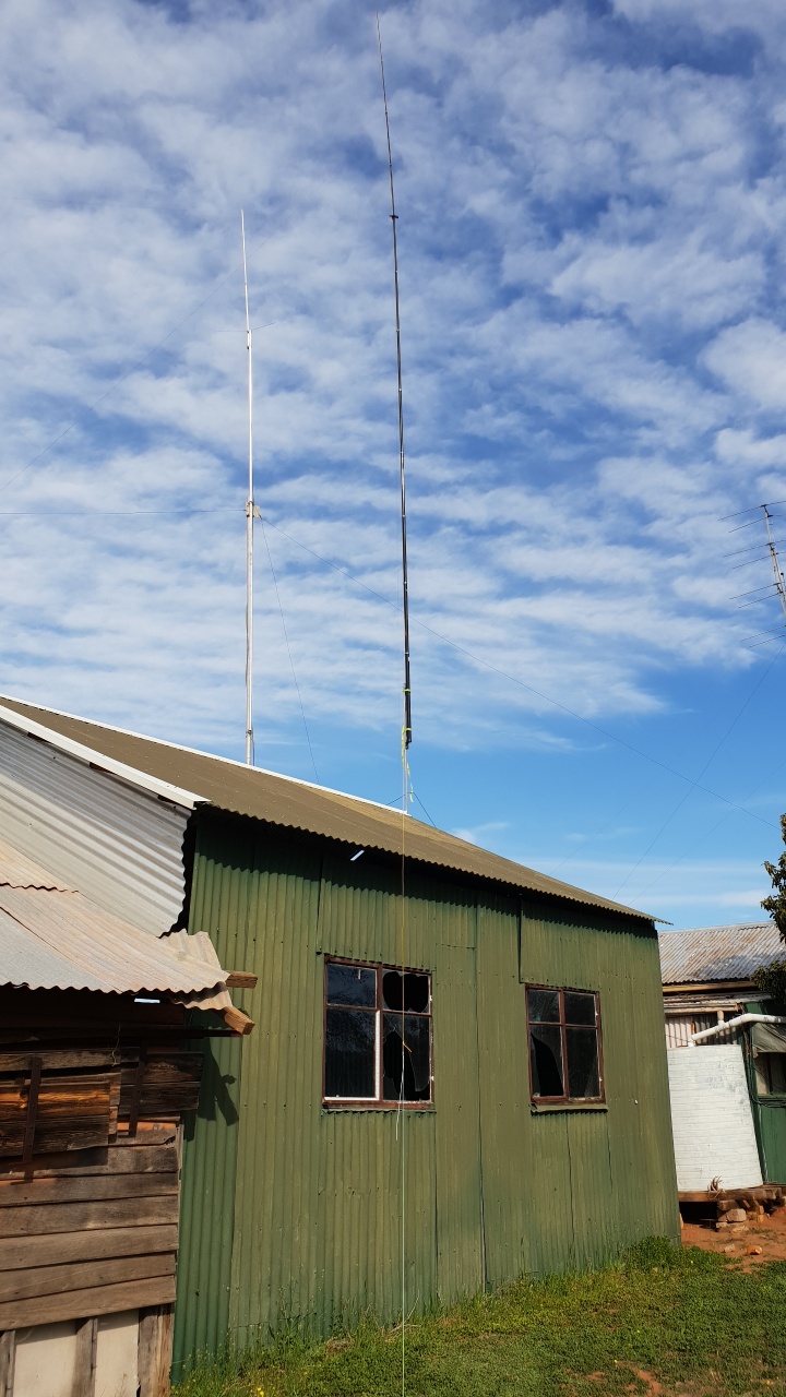
Now, the 2nd lesson for the year – the Gap Vertical Antenna.  It had always been an awesome RX antenna, but I had never been very happy with it as a TX antenna,  So back to basics here.  A double check it was assembled, with the radials as per the instructions.

Assembly was fine, nothing had come apart.   The Manual says at least 3 radials 25 feet long.  I had 5 or 6 that were between 25 and 40 feet long and they were pretty ratty, and most had actually broken.  So first off, replace the radials, with exactly 3, 25 Feet long and  have them off the dirt.

During the year in my reading one thing that I had never taken any notice of before was a comment regarding feeding Vertical Antenna’s – and while I was looking at this in terms of vertical 1/4 wave ground plane antenna’s and the Gap Is essentially a vertical Dipole, I did not think this next step was necessary – How Wrong I was!

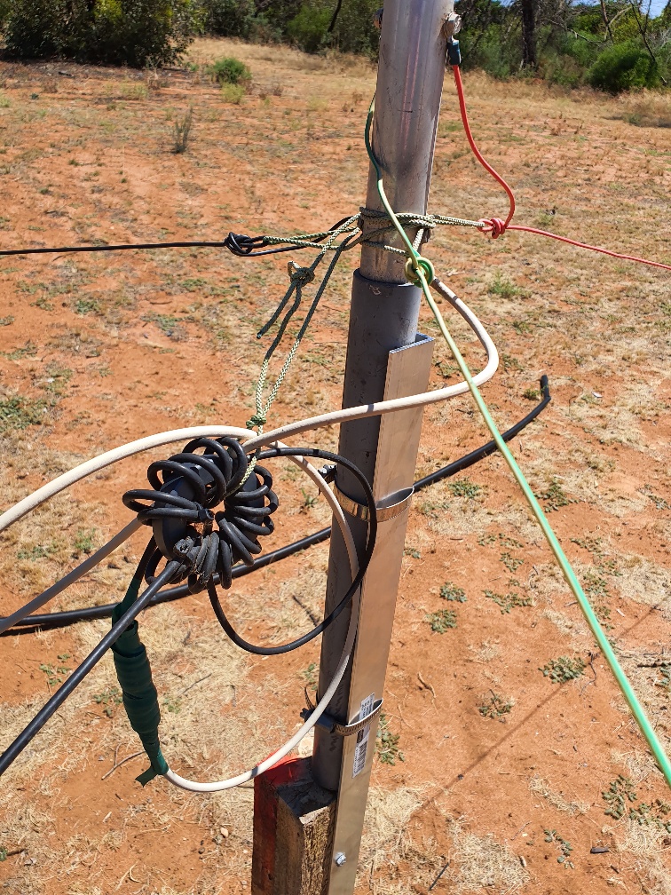
The simple tip – Every single Vertical Must have an appropriate Choke at the feedpoint.   I thought well, why not try this as well,

So, after looking around for the requirements of what makes a good choke, and that I needed to achieve at least 500 ohms (of course more is better) on the bands I was transmitting on to be worthwhile I settled on grabbing a FT240-43 core and with it wound with 13 Turns of RG-58 it provides at least 1K reactance across 80M to 10M.

At worst, this would do nothing, and I would be out the $ for the core, so why not.

feedpoint
The Yellow coax is the feedpoint of the GAP Antenna, Added the Choke and re-terminated the elevated radials.

Well, with choke at the feedpoint, and new elevated radials I threw the analyzer on the antenna.

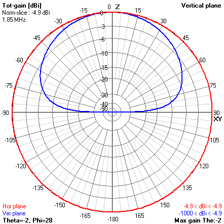
80M – was well out of band and all other bands (40-6) were just fine.

In the past, I was able to tune this antenna on 160 and 80, and all other bands were very close, and could be used without the tuner.  I could no longer tune on 160 or 80,  but the big surprise was using the antenna,  On all bands it was still actually great as an RX antenna, but the big surprise was that it was now actually radiating and in the intervening time It has proven to be a great DX antenna!

I utilized this antenna almost exclusively for the high bands during OCDX  2018.

Yes, that coax, from the vertical across the ground was literally allowing me to match the antenna and was probably absorbing a very large amount of the RF.  I just wish that The GAP manual actually had a comment in it that you in face NEED to de-couple the feedline from the Antenna.

Ok, finally, back to the OCDX 2018 – I worked it pretty hard and the conditions were even worse than 2017 when they were awful!  Thank heavens that this is literally the dead bottom of the Solar cycle, and things should slowly start looking up in the next 1-2 years!

Again, operating QRP was a real challenge and every contact was hard-fought.

2019 OCDX Summary


2018 log summary

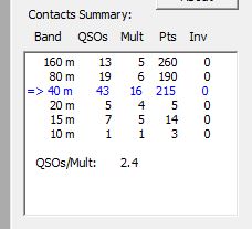
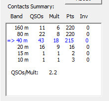
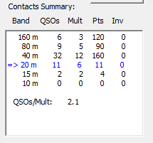
Not a lot of difference between 2018 and 2019, down on 20M, up on 15M and down on the multipliers.

I submitted a log and kept checking the  log page for any other challengers to my score.

My Score as submitted is

VK5HCSingle-Op ALL QRP25419

Yes, that is lower than last year and again, I feel I had better antennas than previous years.

Now, the waiting game until the official results are published.  There is 1 other log that was submitted that was close to my score –

YB3EDDSingle-Op ALL QRP23568

and the next closest was down around 13K.  So the wait is on to see if my logs hold up and my score remains, if so, by a fairly narrow margin I may have done it again this year.

OCDX – of Contesting and Antenna’s

One of the Radio Activites I have really enjoyed over the last few years is the Oceania DX Contest –  where the world points their antenna’s to Oceania and we are the wanted stations.

I have chosen to enter a category of SingleOp All band (160-80-40-20-15-10) SSB QRP.

My first entry was in 2016, and it was basically on a bit of a whim, and I made a handful of contacts, submitted a log and to my surprise  actually came 1-3-3  (Country-Continent-World) with a score of 2660 Yes, First in VK, 3rd in Oceania and 3rd in the world.

This motivated me somewhat to actually put in more of an effort for 2017, and in 2017, my score was 30% higher than the winning score from 2016.  Fast forward a few month’s and my results were  1-2-2  with a score of 10,368.  Yes I had achieved 1 aim of improving my score and this time moved up to 2nd in the world.  The conditions in 2017 were nowhere near as good as the previous year either.

Fast forward to early August (2018) when the 2017 Results were published, and it prompted me again to see what I could do to again further improve my score.

It came down to the 1 thing that I could change – and that is to work really hard on Antenna’s – and that is what I did.

First off, I spent some to time to come to terms learning and understanding how to use 4nec2 to model antennas and started off with the basics – model a simple dipole (Inverted-V) antenna and use it as a baseline to validate  that the model was about what I was seeing in the real world – and yeah, close enough to not get too hung up about things.

Secondly, I modeled the Antenna’s I had used for the 2017 OCDX and this alone was a real eye-opener – and actually really surprised me as to how much of a disadvantage I had put myself at!

My Antenna choices for 2017 were.

  • Titan Challenger 80-10 Vertical
  • End-fed “random” wire of about 57M long and 8M high with a couple of counterpoise wires
  • inverted V on 40 (and also used on 15m)
  • 20m 1/4 WL vertical with elevated feedpoint and radials

The Titan vertical is an awesome RX antenna – but pretty useless for TX – so was hardly used for TX.  The Inverted V – yep NVIS only on 40M and the 20M Vertical was OK.

As I had  done my base learning and modelling of the 40M inverted V, I knew the pattern is all up – so not a DX antenna at all, so I went ahead and modeled my longwire across the 3 bands I used it on.

2017 OCDX Antenna
3D model of the end-fed wire and counterpoise wires

Once I had entered all the data, it was time to run some modelling across the 3 bands that I used this antenna on – and this is where things really sunk in!

160M H and V radiation pattern

At first glance for a simple Antenna on 160M this looked OK, not all the signal was straight up, but then the I noticed the gain – Ouch – -4.9dBi – I was literally taking my 5W of RF and throwing most of it away and effectively using on about 1.5W!

80M H and V Patterns

The 80M pattern was not really a lot better – Again, only 0.6dBi gain  – and the main lobe was pointing in totally the wrong direction for for me to actually use!  with the 90 being North, most of my power was being sent right into the Southern Ocean where there is literally Nobody!

40M H and V pattern

The 40M pattern again was not brilliant – whilst a slight gain of 5dBi when looking at the pattern, it was mostly in the wrong direction again!  where I needed it – there was a nice deep null  where I really needed a signal and probably why in hindsight that I relied on the 40M Inverted V for most of my 40M contacts.

The Challenge

Now, with an insight of how bad the antennas utilized actually were, I needed to look at modelling some better Antenna’s – and the beauty of modelling, is the try before build – which means fitting Antenna’s into the available space I had.  the second Challenge was to do all this and actually build all the required antenna’s within a fairly short period.

40M – (my favourite band)  – I wanted a decent Antenna on 40M as this is a band that I love operating on.  Whilst the dream is a 4-Square array  and yes, I’m fortunate enough to have (just) enough space for such an antenna, I didn’t have the time to build it – so off to the Internet and looking at what I might be able to do given all the restraints I had.

In the end I came up with a 2 Element Vertical Beam – that took me many iterations in 4nec2 to come up with something that met my objectives and was actually a reasonable match as well.

40m Vertical Beam

Now this does not look like a “conventional” beam, given the reflector is 3 segments and not the usual 2. and it is a very “odd” looking shape – but hey, this will become clearer as I explain a bit more.

40M OCDX 2018 H and V pattern

Notice anything nice about this radiation pattern – again 90deg on the circle is North.

Not only have I got a nice wide (about 200 degrees) beamwith, pointing in the desired direction (mostly)but there is nothing wasted out the back, and look at  the vertical pattern is – an awesome DX Antenna.  and with 7.6dBi gain, yet still enough for the up for the close NVIS/single hop contacts.

visualized gain of 40M beam

Not only did I get the desired pattern, it is a pretty darn good match!

Now the reason for the “odd configuration”  Simple, the 12M squid pole supporting the reflector and the top of the driven element is mounted at 7 Metres high on top of a shed,  and I needed to have the reflector split to go each side of the shed.   Nothing more than adapting a design and working it into the environmental’s and space you have available.

The installed 40M beam

Make no mistakes, this is a BIG antenna – the top of the 12M Spiderbeam pole that is supporting the antenna is up at about 19M high and dwarfs the 2M antenna on the adjacent pole.  the photo is taken lookup up along 1 of the reflector elements.

So this antenna was erected a couple of month’s ago and wow –  does it perform!  Very impressed with the results before the OCDX – and the real-world usage indicated that the modelling was in fact very close to the results.

The Low Bands

I spent a lot of time researching as to what sort of antenna’s I could use on the low bands that were going to be achievable in the 4 weeks I had left and eventually settled on a 160M Horizontal loop for a few reasons – mainly because after reading and modelling a lot of different options, this was the antenna I could use and it met (most of) my design objectives.  It is also one of the few antenna’s that the relative performance is much better than a Dipole at low heights – as a 160M and 80M dipole at the 9M height i could achieve with this loop was no better than the random wire I used in 2017.

I did model a few that I would love to build that are in fact much better than a horizontal loop, but ran out of real estate to install it.  Co-incidentally, it was also a very good option for being so close to the ground on the low bands.

The loop was modeled, then the model was re-worked once it was installed to reflect what was actually installed.  I ended up feeding the loop with 300 ohm Ribbon cable, with a short Coax from Radio to a 1:4 balun.   Whilst it is not a perfect match, the Tuner was easily able to achieve a decent match on both 160 and 80, and the analyzer gave me a good indication that It is in fact resonant where I needed it on these 2 bands.

160M H and V pattern

Now while this pattern might not seem like it is a big improvement over the 2017 one – it actually is  a massive improvement.  Yes, it is a lot of straight up, but it is 1.4dBi gain – or a 6db improvement over the previous year – and where every watt counts…

80M H and V pattern

Again, at first glance, 80M doesn’t look to be brilliant, but then again – a big step up from the previous year with around a 3db improvement.  The nothing straight up was not really a hindrance to how it performed and it was remarkably good.

The Higher Bands

For 20M this year, I opted for a Full wavelength dipole  with the 3/4 w/l leg pointed at around 120 Degrees.  this antenna provides a broad “beam” with around 5db forward gain along the longer segment at reasonably low radiation angle and a bit of F/B. – Again, not the “perfect” antenna, but proved to be better than the previous year.

Given that 20M is literally  the POWER band I was simply hoping to grab a handful of multipliers here and If I worked 10 I would be happy.  I did miss out on a Short Path EU opening because I had the antenna fixed in a single direction and if I had anther antenna or been able to quickly re-orient this one may have picked up a few more contacts.

I used the 40M antenna on 15 as well – and yeah, some more effort needs to go into the modelling of the antenna to see if the 15M could be improved without degrading the primary band, or of course build a better 15M antenna – something for next year.

15M pattern from the 40M beam


This year, the gap vertical was again used  but mainly for RX, with exactly 2 contacts on it – 1 on 40M to VK7 where I am at a slight disadvantage on the Beam and 1 on 10M.

Honestly, I did not put much effort into the high bands (15 and 10) given the band conditions and unlikely chance of a decent opening on these bands.

The Results

Well the proof of the modelling and antenna effort was well and truly rewarded.

This year, the conditions were nothing short of horrid yet I was able to nearly triple my score and my submitted score  this year is 29,068

2017 Log Summary
2018 log summary

The bottom line  is and, what I hope is the take-away after reading this post is Antenna’s matter – and if you take the time, model what you have you can (generally) work out how to do something better than what you may already have in place.

Final word – I enter QRP not because it is easy, but because it is hard!

VK5 is of course also at an added disadvantage – given that we are 1 hop further away than the other states – and over land and not water, further compounding the need to maximize our Antenna efforts.

I missed out on a heck of a lot of potential contacts because in am 20+ dB down with my power, but I had a blast actually doing what I did.

Update 12/10

I forgot to mention and now adding it in here.

One of the issues I had last year was my callsign – VK5FO – Whilst it has a certain charm and schoolyard smut factor, it was actually a problem during contests.  I spent a fair bit of time, listening to the bands, listening to callsigns and then went and looked at available callsigns.

I applied for and was Granted VK5HC (Hotel Charlie,  Henry Charlie, Honolulu California, or my favourite – welcome to the Hotel California) and yes, the callsign makes a difference when you are (I am) on the RX stations noise-floor). The callsign choice probably helped me actually complete 5 to 10% of the very difficult contacts.

A “contest callsign” that is phonetically easy is a worthwhile addition

2017 Summer FD

This year,  for something a bit different the FD was never about building a full-on 4 band station and going all out for a big score – it was all about doing more with less.

We (Me, Bob VK5FO and Ray VK5RR) teamed up with Andy, VK5AKH and went QRP portable and went for a “nice” hike up to Black Hill Summit – a summit that is a hike in – and at 460M above sea level in PF95ic

We met down the bottom of the hill about an hour before the start and packed up the gear and antennas and away we went

We were taking gear to get us on the air on 4 bands for field day – 6m, 2m, 70cm and 23cm.

After nearly an hour, we finally made it to the summit at around 01:10 UTC just after the start time and proceeded to set up Antennas and Radio’s

Here you can see the Antenna’s – 1/2 Wave Vertical for 6m on the blue pole, and on the Camera Tripod, you can see the 11 Ele on 23cm, the 6 Ele on 70cm and the Slim Jim for 2m.

Andy making a contact on 6m with the KX3.

The summit, while it doesn’t offer great views has shade! which makes for a pleasant place to operate from.

Did I say minimal station set-up.  Here I am with the KX3 and you can see the 70cm XVTR and batteries in the foreground.

We were set up pretty much at the old trig point – I say old, because someone has ripped it all out of the ground at some point and built a pile of rocks adjacent to it on the walking trail.

The aim of the day was to enjoy the hike up to the top of the hill and play a bit of radio and within an hour or so we had contacts on all 4 bands.  It was all about getting out for a few hours, and getting a few contacts and handing out contacts to the other stations who were also out and about.

As far as FD goes, it is a decent location for a minimal set-up basic antenna’s that we carried in, and very modest power  on all bands – we had 5w on 6m, 2m and 70cm and 3w on 23cm.  It truly is a case of “height is might” when it comes to VHF/UHF and above.

Mid-afternoon we packed up and headed back down the trail.

It doesn’t look it, but it was a decent hike – with about 2km each way and 250+M elevation change.  Coming back down was a bit quicker it was only about 40 minutes. Here we were about 5 minutes from the bottom.


We had APRS running on the Handheld while hiking in and out.

At the end of the day, I logged 16 contacts for FD, and Andy logged 21, in the 3 hours or so we were at the Summit.

As we were operating from Black Hill, this also qualified as both a SANPCPA and VKFF Activation.


Team VK5FI

Well, for something completely different.

Team VK5FI is VK5RR and VK5FO, and FI is ‘5RR’s other callsign.

We decided to have a go in the VHF/UHF Spring Field day.  With the introduction of the (up to) 4 band section, and having both reasonable power and antennas for the task on the 3 low bands where we put the station together over a few weeks and yesterday morning got out and had a good solid go in the 8 hour section.  The intention was to operate SSB and FM on 6m, 2m and 70cm

For the location, we decided on the Ardrossan lookout at PF85WN – which is about 80km (los) across the Gulf back to Adelaide.

spring-vhf-uhf-2015Screenshot from contestradar

Now a little about the station we put together

The Common Equipment

To power the station we had a 165aH AGM 12V battery, and A huge thanks to VK5AKH for the loan of his Honda Generator – which we used to “float” the battery and to also provide power to the logging Laptops – we had no issues at all with power for the day.

We had the battery in the trailer, which also served as a support for all the antenna’s.

The station consisted of 3 txcvr’s – 1 for each band we were operating.  All 3 Radios used have remote heads, which makes setting up a lot easier than having to set up right next to the battery in the trailer!

We used the Armstrong method for rotating the beams.

The 6M Station

The station was quite simple – we put back into service the ancient IC-706  and coupled to a 2 Element Beam (horizontal), running a full 100w.

The antenna was on the same pole as the 70cm beam and up at about 4m High.

The 2M Station

On 2m we used the IC-7100 feeding a 6 Element Beam (Vertical) on it’s own pole up at around the 4.5M mark.  After about the first 2 hours, we realized that when you unplug the remote head from an IC-7100, that it reset the output power – so for the first 2 hours, we were only running 1W output instead of the intended 50W!  (and surprisingly, we did not really suffer too much as a result).

We also put up a Slim-Jim vertical at 10M high for 2m and had it connected up to a handheld, but in the end did not use it or the contest.

The 70cm Station

On 70cm we opted to us the TS-2000 – as it is the highest power we have on this band.  It was coupled to a 17 Element short boom yagi (approx 2m long) and put on the same pole as the 6m antenna at about 5M high.  We set the polarity to be 45deg – so not truly vertical or horizontal.

We arrived at the Ardrossan lookout with a bit over an hour to set up.

20151114_101028

Overlooking the Gulf from the lookout with the antennas on the roof racks.

So, we positioned ourselves where we could set up and operate and also so as not to be in the way with other visitors to the lookout and set up the station.

20151114_114435

The station, set up and ready to go.

Just out of the photo to the left we set up the generator near the rock,  The trailer – it has the battery in it and also supports the 2 (3*) poles for the antenna’s.  The plastic box on the draw bar contains the 3 transceivers – all close to the power source!  On the Other side of the car we tied up a tarp to provide shade over the table we set up to operate from.

The 3rd pole was the 12m spiderbeam pole with the 2m Slim Jim.

20151114_115214

The other side.

20151114_114454

The trailer with the battery and the poles for the antenna’s – and under the tarp is ‘5RR starting to operate on 2M.  The esky was lunch!

We did a simple split – based on the antenna’s – Ray operated the 2M station and I contended with 6m and 70cm.

We were able to plod along and work a reasonable number of stations from this location.  For the most part on all bands we were able to simply leave the antennas pointed (roughly) at Adelaide, but there were a few exceptions where it was necessary to swing around to the North to make contacts.

The day was not great and the wind was quite strong and at around 5:30 the wind literally ripped the tarp to bits!  We had to take a bit of a break and move from the table into the car to keep operating.

With all stations having remote heads, this was not too much trouble to do – just pick up each remote head and feed them in the back of the car.  It made the rest of the operating more difficult.

According to VKCL we ended up with:

6m –  33 contacts
2m – 48 contacts
70cm –  51 contacts

Lessons and Improvements

Now, we are not really big VHF/UHF operators and it has probably been around 20 years since we did any sort of VHF/UHF contesting, let alone operating portable like this.

A decent, high operating point is a real advantage and having additional antenna gain was most welcome.

2 operators would still be easy to add a 4th band to the mix.  The combination of 6m and 70cm worked out ok.

The Good
  • It was a Fun day out!
  • We made a decent number of contacts on both FM and SSB on the chosen operating bands.
  • The set-up proved to be effective – set up in about 45 minutes, same for station pack-up.
The Improvements
  • Antennas for each band on their own pole.
  • Headphones/headsets!  With 2 operators literally sitting next to each other, and all 3 radios turned up at the same time it was difficult at times to hear.
  • Antenna’s – with the wind they moved around a bit!

For this sort of operating, on even these bands we literally pulled together all the gear we had at short notice and went out to give it a go.  It was obvious that there were stations we could not hear from our location and we later found out that there were several stations in the metro area using nothing more than a handheld – these are the one’s we could not hear.

Even the very modest home stations we were able to work in the Adelaide metro area.

For this style of operating, we had about the right mix of power and antenna gain from where we were.  We had no real issues of interference between the bands, maybe a little be of de-sense but nothing too be worried about.

The antenna choices were proven to be effective – vertical polarization (except 6m – we didn’t have the mast height) and the boom length on 2m and 70cm meant we could rotate them without it physically interfering with the other ones on the other pole – it was not necessary to go larger in this case.  It might be a different story if there were stations further afield that  you were chasing – but with the majority of the activity within close proximity to the Metro area  it was a good mix of being both physically easy to manage and gain.

A review on the logs and we determined that the range of all stations worked was between 61 and 158km from us.

Update – The Results


Division 1

 Portable Loctn: PF85WN - Ardrossan Lookout

 L'tors Actvtd: PF85 

 Section: B2b: Portable Multi-Op, 8 hours, Four Band

 Division: 1: Locator Based Scoring

 Operators: VK5RR Ray, VK5FO Bob

 No.of Contacts: 132

 Total Score: 792

Division 2

 Portable Loctn: PF85WN - Ardrossan Lookout

 L'tors Actvtd: PF85

 Section: B2b: Portable Multi-Op, 8 hours, Four Band

 Division: 2: Distance Based Scoring

 Operators: VK5RR Ray, VK5FO Bob

 No.of Contacts: 132

 Total Score: 24037


2015 QRP hours contest

Last month, on Easter Saturday I participated in the QRP HOURS Contest for 2015.  This year, the contest got a bit of a boost with promotion among the many portable activators including SOTA, VKFF and SANCPA Yahoo Groups.

The concept is simple, it is 2 hours long, split into 2×1 hour categories.  The first hour is CW and Digital including PSK31 and RTTY, the 2nd hour is Phone (SSB) and is on 80M.  Rules are simple, QRP stations (5W CW/Digital or 10W SSB) get 1 point for every station worked and no repeats.

Given the very nature and the fact that the noise floor at home is only s9 when it is quiet, I headed up to my favorite SOTA summit, Mt Gawler, VK5/SE-013  for the contest.  I decided on this for 2 reasons – the obvious being that the noise floor should be a bit lower than home, and the fact that nobody had done an 80M activation of this summit.

Arriving only 15 minutes before the start (nothing like being prepared) it was a bit of a mad scramble to get everything set up, got the table out, set up the laptop with the KX3, then rolled out the 80M dipole and hung it up a 9M squid pole at around 8M.  I should have planned better and borrowed a 12m pole to get the antenna a bit higher, but hey you do what you can.

Saturday night was pretty chilly up on the hill and it was down around 10deg and a decent wind made it feel more like zero!

Only 2 minutes late starting, I finally got on air running PSK with only 3W to find a reasonable number of signals.  Now, I was going ultra-low-tech here and was only using the KX3 Utility program and relying on the built-in features of the KX3 to decode signals.  Yes, no waterfall display, just tuning the approx 3khz and trying to land someone calling cq.

The difficulty here was that I had never actually had a PSK31 contact using the KX3 beforehand so other than reading the manual and watching a few YouTube video’s on how to set it up earlier in the day I was totally unprepared for the first hour.  As a result, I probably did miss out on at least 5 or 6 more contacts that went begging during this hour.

It was pretty tough operating like this, and there were quite a few incompletes that I did not log.  Yes, there was a bit of noise about on 80M, but still nowhere near as bad as at the home QTH.

It was only moderately successful as far as the contest was concerned but did manage to complete 4 contacts, VK1, VK3, VK5 and VK6.  from a SOTA perspective, this was great, I qualified the summit on 80M DATA – 2 firsts for this often activated summit.

Qrp Hours 2015 Mt gawler
Headset – check, Foot switch – check, Torch – check. Everything in order contesting /p


SSB –  the 2nd hour

At the start of the 2nd hour, I unplugged the computer, cranked the power up to a massive 5W and went about doing the “hunt and peck” and worked the 5 or 6 stations whom I could hear across the voice segment.  As soon as I had worked as many as I could, I found a clear frequency and started calling CQ.  It was a case of calling and waiting for them to come to me.  There were bursts of activity and long periods of no replies and the unfortunate fact that with storms between VK5 to the East it made some contacts quite difficult!  There were probably a lot that I missed out on no doubt.

At the end of the night I had 23 contacts in my log, only to find that on checking later there was 1 dupe, so it will not count towards my score, with contacts to VK1, VK2, VK3 and VK5.

I already know that there were several other stations who managed bigger scores than myself – as 1 serial number I was exchanged was 39 – and that was about the 42 minute mark!

This sort of contesting taught me quite a few things and things I could have done better

  • Get set up early!
  • Make sure beforehand how to operate a particular mode
  • Antenna, Antenna, Antenna
  • Trial the location beforehand

All in all it was a somewhat cold, but interesting evening of Radio Sports and yeah, Like Arnie say’s “I’ll be back”