Over the last few days I had the opportunity to borrow a 40m Transmitting Magnetic Loop Antenna with a big thanks from Steve – VK5SFA for the loan of his 40m loop so I could conduct some comparisons.
We were at the shack in PF95wu where I have the GAP Challenger Vertical and where I could put up my portable 40m Inverted V antenna.
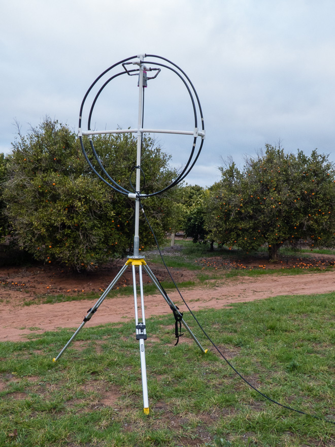
VK5SFA 40M loop
The loop is physically quite small at only about 1.6m in diameter – and as you can see it was mounted on a tripod with the bottom only 1.8m off the ground, and as far away as my coax would allow from the shack – which was about 10 or 12 Metres.
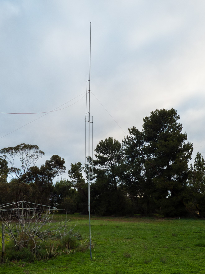
Gap Challenger Vertical 80-2m
The Gap Challenger, which has been put to use as the primary RX antenna for the KiwiSDR – was one of the comparison antenna’s used over the few days.
For the TX experiments I used the KX3 and HR-50 Amp and was transmitting at between 40 and 55 Watts of power.
Observations – the Loop
The bandwidth of the loop was quite pronounced – tune the loop, tune the RX across the band and it was pretty obvious – about 40khz wide.
TX – well, it was nowhere near 40Khz wide – more like about 12 or 13khz 1.5:1 VSWR bandwidth.
The first night, we had a bit of rain earlier and the ground was a little damp. We found it impossible to actually tune the loop – best we could get was about 4:1 VSWR on TX. The next night it was much better!
Tuning – well touchy is an understatement! The tuning is manually done via an insulated rod – and 1/4 of a turn was like 40khz! It was a case of tuning for maximum RX noise, then some careful fine-tweaking to get it there.
RX Bandwidth
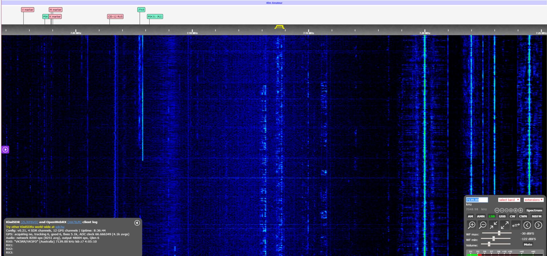
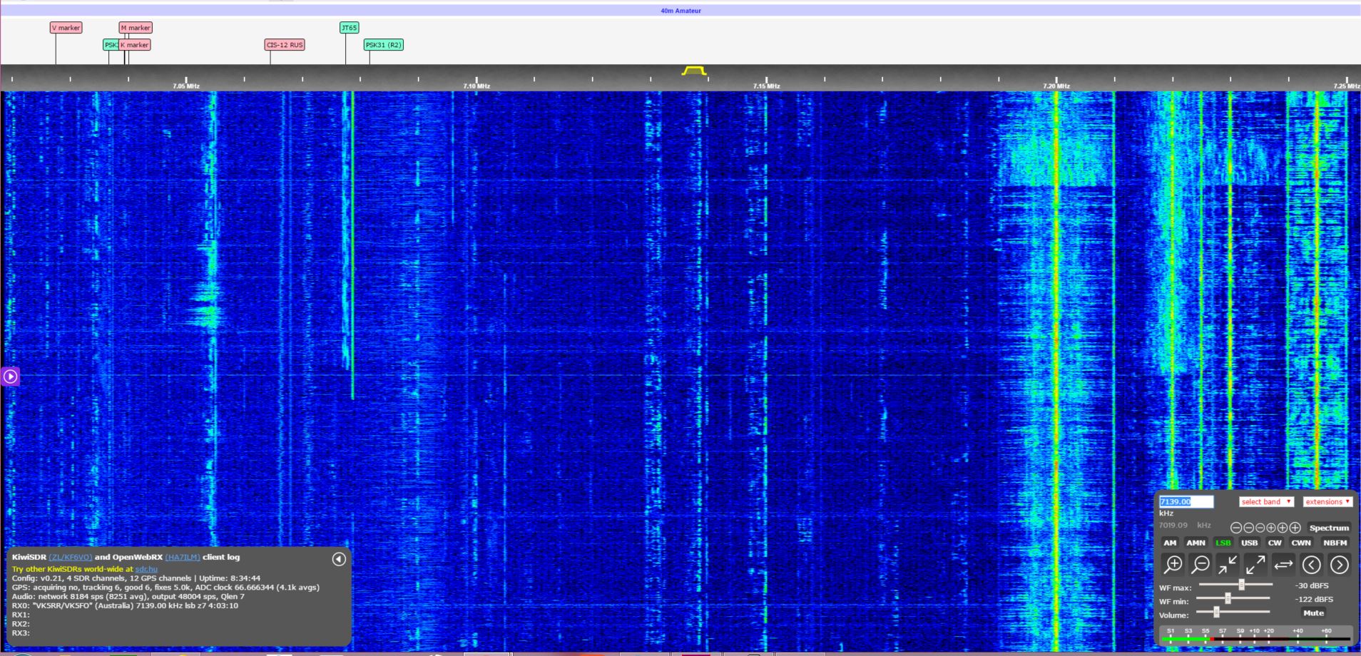
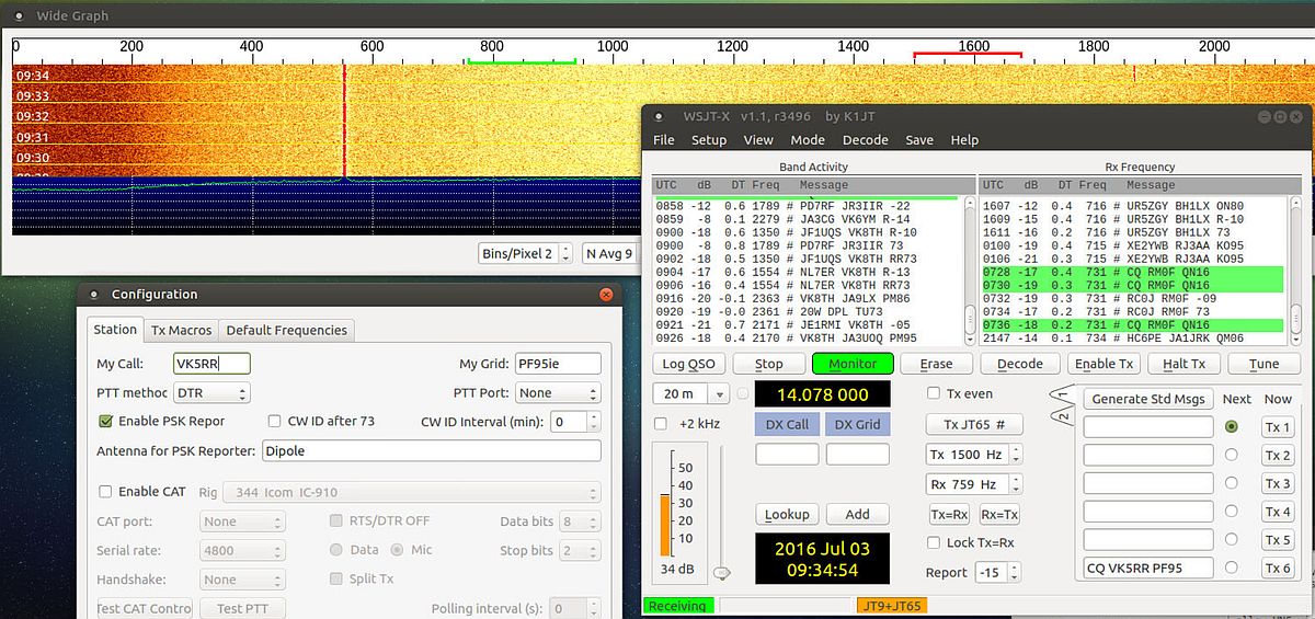
The Loop was tuned to 7.140 and plugged into the SDR
40M loop on SDR
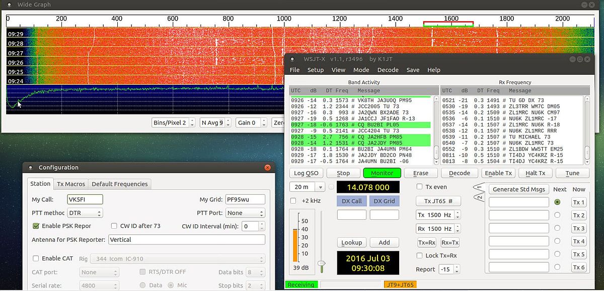
Without changing any settings on the SDR, the Vertical was plugged back in.
IT is pretty obvious as to the RX bandwidth and how sharp it drops off away from the centre frequency.
Click on both Images to see full sized.
Usage
I made use of the Loop to talk during the day – local, single-hop contacts (VK2, VK3, VK4) – and when 40m is open, it is open – 59 contacts – no real difference between any antenna. DX – I did have a couple of contacts to the West-Coast US using the Loop – and got respectable reports back based on my 50W!
The Loop has 2 large lobes, and quite a deep, but fairly narrow null on each side. The null is about 50-60 degrees and 2 S-points – or probably around the 12db mark (give or take). We did have a little bit of local noise, and rotating the loop we observed the noise drop right off to S1-2 when nulling the noise.
Side by side, with the Vertical – RX was on par, and TX was much better – just because there is a slight directivity associated with the loop .
Side by side with the Inverted V – well this was much more interesting – The Inverted V was only 8m high with each end about 2m off the ground.
The Inverted V was 2-3 S-points noisier than the Loop, but also 1 S-point stronger on the signals. With an S6 noise and S9 Signal for the VK contacts, versus’s the loop, with an S3-4 noise and an S8 signal.
It clearly had at least 10db better signal to noise versus’s the Inverted V – and well, hands down beat the Vertical on TX!
The far stations reported slightly stronger signals on the Inverted V, but I don’t hold much faith in that as there was heavy QSB – I would call it a tie.
Conclusions
I would conclude that it is about on par with a dipole in typical performance – but has a considerably smaller footprint! I was actually not expecting that the performance to be as close to the Dipole/Inverted V as it actually was – remarkable considering that you only need a very small space to have the equivalent of a rotatable dipole!
For the Amateur who is space-challenged or has a lot of noise, then yes, a loop is certainly worth considering for the low bands.
As we have the Loop for a couple more days, we will set it up in a typical urban lot – where we simply cannot use 40m as it is always S9+ noise and make some observations as to how effective it is in a much noisier environment.
So, after seeing a few Kickstarter updates and knowing that there were a handful of beta/test sites out there I decided to make contact with the Project Owner – John, ZL/KF6VO and put together a “proposal” to offer up the site as another beta test site.
Well, as luck would have it, John was happy to work with us for a couple of reasons – He had just 1 of the 10 boards left from his initial beta production run and he did not have a beta test site in VK.
After discussing details for a little while John sent the KiwiSDR and we have installed it onto the Gap Vertical Antenna in the Riverland.
Since it has been installed, we have found that the RX to be quite sensitive – quite surprising really! The software is really quite easy to use as well.
It was a real eye-opener to “see” the whole 30Mhz of spectrum in the band scope display and realize just how much local noise there is at our site!
We know that there are still some software issues and within 24 hours of installation a further software bug was found and the auto-update rolled out the new version of software.
We are still waiting for a nice and quiet (rf-wise) linear power supply to arrive, and have it running with a fairly noisy switched-mode supply. As soon as we can this will get swapped out and hopefully improve things even more.
The Rx front-end is very sensitive to local noise – and we found that on power-up we had a very high noise floor. We found that the noise was simply that the Ethernet cable crossed over the Antenna coax cable – and it introduced over 40db of noise, so some careful re-routing of cables was done and we saw massive improvements.
Yes, there does need to be careful consideration of the installation and we could probably do a lot better than the simple protective case the SDR is in – we will probably put it into a decent metal case that is earthed to further reduce any local noise getting into the front-end in the near future.
Our previous experiments with JT65 had already proven to us the advantages to be had with running a remote RX site, and having the whole HF band available with the really simple and powerful interface has been great!
At the price-point, it is a great SDR – and much better than a simple panadaptor that only shows a single band – It is going to be one of those “Must Haves” for your Contest Station!
A little about the interface itself – Very easy to use – a simple point and click – select mode, select zoom on band display, enable/disable spectrum display, drag the audio passband – a continuously variable filter set the low and high cut frequencies to suit. Easy to adjust the Waterfall min and max sensitivity – once you set it for the band/noise floor it is really easy to “see” what is happening.
Whilst there is no noise filter, I have found that small adjustments to the audio passband can make a big difference.
There are now about 10 of the KiwiSDR’s around the world – so have a play – you will probably go off and order one for yourself! I will probably be getting a 2nd one after seeing how good this is!
… and just in case you have not already found it –
Over the last several weeks we have been running an experiment – an experiment that is all about doing the same* (similar) thing at different locations.
We are fortunate enough to have more than a single QTH where we can set up an amateur station, so we have done so.
Station 1
We set up Station 1 at our Main home QTH in the City – in PF95ie
The station consists of the following
Kenwood TS-2000 TXcvr
Dipole at 11m high (running North/South)
Pine64 Running Debian Mint and the current version of WSJT-X into a USB sound card.
Station 2
We set up Station 2 at our shack in the Riverland, approx 160km away in PF95wu This is a semi-rural location with less than 50 houses within 1km, but in an active irrigation farming area (think pumps switching all the time)
The station consists of the following
Icom IC-706 (yep the 20+ year old original version)
GAP Antenna Challenger DX Vertical
Pine64 Running Debian Mint and the current version of WSJT-X into a USB sound card.
As you can see both stations are very modest – and what I would call Atypical of what someone might have installed. There is not a lot of differences between them – but, granted, there are differences.
We chose to do this experiment with JT65 simply because of the ease of setting it all up and having it automatically report the results. We could have probably done the same and set up a similar experiment with WSPR, but chose JT65 as you can actually have a “QSO” using this mode.
We wanted to set up the stations to reflect what would be reasonably easy for almost anyone to set up and have working with a minimum of fuss – just using whatever antenna you have and whatever TXCVR you have as well. Ah yeah, also, to put a couple of VK5 Callsigns in the reporter list so the rest of the world knows we exist 🙂
As a point of interest, we have had the Vertical antenna and the same dipole installed at Station 1 for several years, and never really had much luck with any contacts on the vertical – it was always a lot noisier in the city than the dipole. The only advantage it gave us was it is no tune, all band.
The Experiment
We set up both stations to operate 24/7 on 20m listening to JT65 segment of the band on 14.075USB, both Stations were tuned to show the same signals in the waterfall – so as not to distort what is being heard by each station. Both stations have the pre-amp on, bandpass filters set to 3khz, no noise blanking or filtering enabled.
Both stations are set up to report to PSK reporter so we could collect the data and analyse the results.
Station 1 is set up using the callsign VK5RR and station 2 is set up using the callsign VK5FI and they have both been running for a few weeks now, It did take a couple of weeks to get the 2 stations set up so that they were stable and pretty much on the same frequency
While we were setting up the baseline so we could see some results we were simply monitoring pskreporter and making a mental note of the results. Once we got to a point of seeing consistent results from both stations with them both up and reporting for more than 2 weeks, we have started grabbing some stats from PSK reporter and assembling them over the last few days.
The Results
Well, the experiment is ongoing, so results are simply a snapshot in time of our observations over the last few days.
As this experiment is ongoing, you can view the results in real-time yourself. follow the 2 links below, select Band, 20m, Mode JT and the desired time window.
Strictly speaking, since the experiments is still ongoing there are none – but simply some observations of the results that we are seeing.
The 20m band (winter propagation) does shut down for significant portions of the day.
There is significant differences in the observed results for each station
Station 2 has much better “ears” than Station 1 – considering that our usage of the Vertical has been disappointing over the last several years
City locations with the inherent HF noise floor (which is evident in the images above) are not such a good place if you are wanting to use HF.
It is interesting to observe and note what time of day favours what part of the world – it is pretty easy to see when the band is opened to where in the world.
So, where to from here, that is easy, the next step will be to put up a dipole at station 2 and make observations over another week or 2 and see if this has a significant impact on what is being heard.
One thing for sure, we really need to spend a bit more time on our remote station and HF might just become one of those things that is not beyond reach.
If you are like me and drive a modern car then the simple task of powering your radio(s) in the car become somewhat of a problem. Gone are the days where it was trivial to run a cable thru the firewall and connect directly to the battery, so time to think differently.
First off I didn’t want to drill or cut holes to run cables, second, I wanted a little bit of protection. So, a little bit of thinking and it was option 2 – add a second battery specifically for the radio. This of course leads to other issues – of management (charging and not over discharging. I could have gone out and spent several hundred $ on a Battery Isolatoin solution – or I could come up with something myself.
The Problem
Now, the requirements for mobile power are reasonably simple – I run an APRS tracker in the car – so a 2m txcvr, that draws about 0.5A on Rx and around 7A on Tx for 3 seconds every 2 minutes. The other requirement is the HF/VHF/UHF mobile txcvr (IC-7100). The ‘7100 draws around 1A on Rx and up to 22A on Tx (but more like 10A on VHF/UHF).
First off – the good old 12V plug (cigarette socket) is not so great – in the car, with all sorts of unknown management, we discovered that the voltage varied between about 10.5V and 14.2V when the car was on and running and often drops down to sub 10 when drawing more than about 6 or 7A or so. This made the car provided DC useless!
The Solution
Time to look at how to use this unreliable power to keep a 2nd battery charged, whilst also not allowing the 2nd battery to over-discharge.
So, a simple plan was put in place to put together a suitable charger and battery manager.
The solution in the end was quite simple (and came out a lot cheaper than a commercial solution.
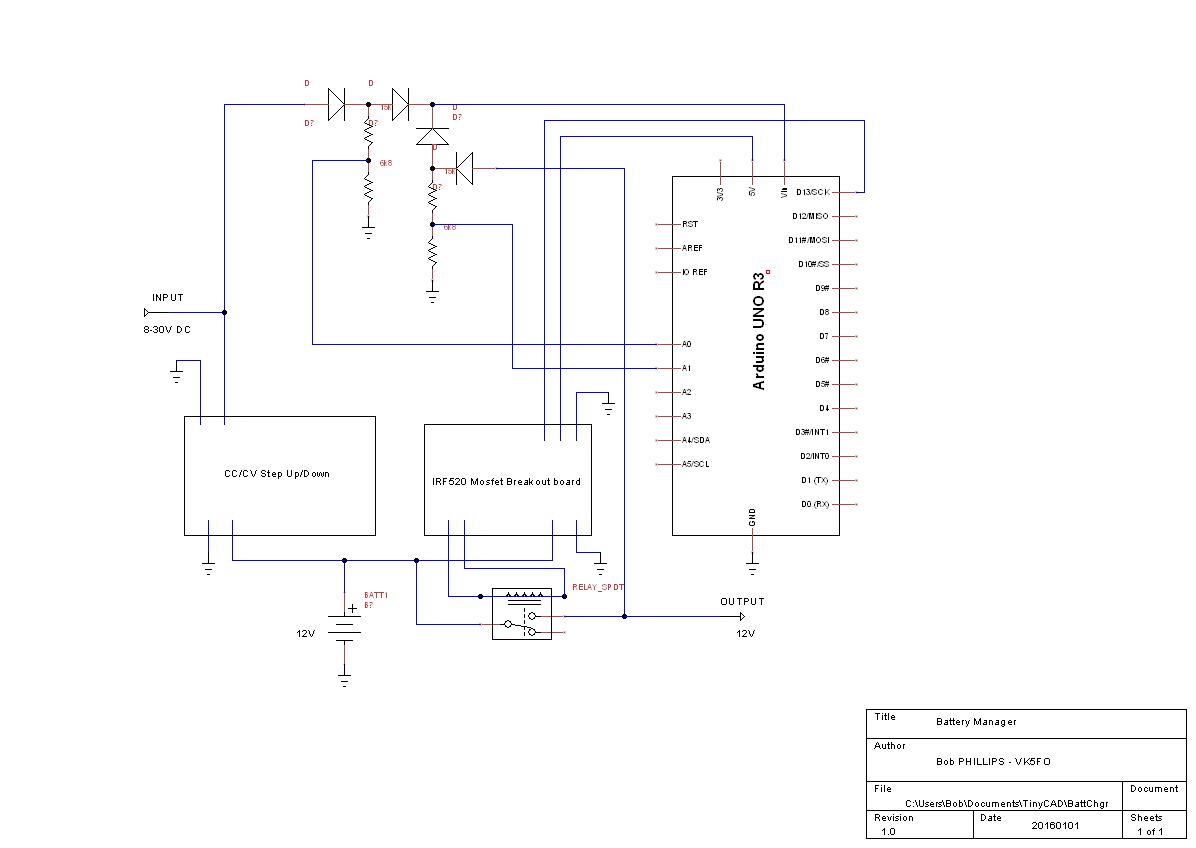
Schematic of battery management solution
I knocked up a fairly simple, straight forward circuit and sourced all the components/building blocks that I needed.
The Components
Arduno Micro controller – I used a Nano (but a Pro Mini would also be suitable)
40A 12V Automobile SPDT relay – I got one in a holder with leads
DC Step Up/Step down converter with CC/CV output
Mosfet on a breakout board.
4x Diodes
2x 15k and 2 6k8 resistors
A piece of vero board
Hookup wire and various connectors.
I sourced most of these items from Ebay, my junk box or a local retailer for literally a few $ each.
I chose to put an Arduino Micro to the (simple) task of managing my battery – more on this shortly.
I found a suitable DC/DC converter that met my needed criteria: It had to have an input voltage range of at least 8-16V and output of 10-15V at 5A. I found one on Ebay was 1.5-20V input and 5-32V output at 5A. It had both a CV and CC adjustments – so It meant that I could set the output to 14V and limit the current to 5A.
The relay was similarly sourced from Ebay, On testing it, I found that the relay I obtained required about 140ma to operate it. So that would require a suitable transistor/FET so that the Arduino micro could drive it. Again, off to Ebay was the easiest solution was a simple break out board with a MOSFET. I found one for about $1 that had an IRF520 device. A quick look at the spec sheet and it is a massive over-kill for this task, but given the $ and the convenience of already being on a breakout board, ready to hook up I grabbed a couple.
Now the only part I really needed to think about, and then it was not even a lot – was monitoring the input voltage, battery voltage and powering the Arduino.
Monitoring battery voltage is trivial – just a simple voltage divider for input to one of the ADC Inputs.
Powering the Arduino – well this is where I get a bit creative – and fell back to using a handful diodes to provide multiple DC sources to power the micro. This will make sense why I did it the way I did when we get to the code for the micro. Given that I only needed to isolate and supply less than 10ma I went with some 1N4148’s that I had.
Circuit Operation
It really is quite simple when you look at it.
Input power to the DC/DC converter and it will charge the battery. This input comes from the car – yep that horrid 12V socket.
We also take the input and feed it thru a diode, to isolate it for a voltage divider for monitoring the input voltage on A0 of the Micro, then thru another diode to the Vcc pin on the Arduino. The Nano has an on-board 5V regulator and is quite OK with up to about 15V input.
When the Arduino has power, it can start running the code.
The first thing that the code does is to drive pin 13 high – which goes to the MOSFET, and in turn enables the relay.
Once the relay is on, we take some of the output, and again with our diode, we isolate a voltage divider to feed A1 of the Micro, then thru another diode to the Vcc pin.
Now this might seem a bit counter-intuitive – but it is not! We have supplied 2 possible power sources to the micro – which is monitoring and managing our 2nd battery, and more on that when we look at the code.
The Code
I decided that whenever there is an input voltage (ie the car is running) that I would turn on my 2nd battery, and it would remain on for 7 minutes after stopping the car as long as the battery voltage was over 12.05V
/*
* Battery Charge Controller
*
* Bob P 20160101
*
* V 1.0
*
* Monitor Charge/Input voltage
*
* Monitor Battery output voltage
*
* Turn off output voltage if:
* 1. Charge voltage off for more than xxx minutes
* 2. Charge voltage off and bettery voltage less than xx.xxV
*/
// Init all variables
int CHGvolt = A0; // A0 charge voltage sensor
int Battvolt = A1; // A1 battery votage sensor
float CHGread = 0; // Variable to store chg voltage
float Battread = 0; // Variable to store Battery votage
float volts; // Variable to store voltage Divider value
long ShutTmr = 7; // Minutes until shut down when loss of Charge voltage
float LowVoltCut = 12.05; // Battery Low voltage cut-off
long UntilShut = 0 ; // Count down timer until we shut down
bool StartShut = false ; // Start the shutdown timer
void setup() {
// set up voltage divider values for ease of maths
volts = (float)6800 / (6800 + 15000); // gnd, 6.8k, measure, 15K, +vcc
// Serial for debug only // comment out when in use
Serial.begin(9600);
}
void loop() {
// put your main code here, to run repeatedly:
// See if shut down timer has expired
if ( millis() > UntilShut ) {
digitalWrite(13, LOW); // Time out has expred, shut down
}
delay(5000); // let everything settle before we do anything
// read the CHG Voltage, convert to Actual Voltage
CHGread = analogRead(CHGvolt);
CHGread = (CHGread / 1024) * 5 ; // 10 bit DAC with 5V reference
CHGread = (CHGread / volts) + 0.8 ; // Actual input voltage, including 0.8v diode drop
// read the Batt Voltage, convert to Actual Voltage
Battread = analogRead(Battvolt);
Battread = (Battread / 1024) * 5 ; // 10 bit DAC with 5V reference
Battread = (Battread / volts) + 0.2; // Actual Battery voltage, including shottkey in relay
// OK, lets look and see if we have a charge voltage
if (CHGread < 8.00 ) {
// we have lost input/charge voltage
// If we have not already commenced a shutdown, time to do so
if (!StartShut) {
//Serial.print( “starting shutdown.. “);
StartShut = !StartShut;
UntilShut = ( ( ShutTmr * 60 * 1000 ) + millis() );
}
// Now we look at the otput voltage and kill it if the voltage is too low
if ( Battread < LowVoltCut ) {
digitalWrite(13, LOW); // Kill the output
}
} else {
// So, our Charge voltage is good, we reset shut down time and cancel the sut down
if (StartShut != 0 ) {
StartShut = !StartShut ;
//Serial.print(” Shutdown Cancelled ” );
}
// reset our shut down timer
UntilShut = ( ( ShutTmr * 60 * 1000 ) + millis() );
//re-enable the output – if it was shut off due to low voltage before timer expired
if ( digitalRead(13) == LOW) {
digitalWrite(13, HIGH);
}
}
/*
* Debug print block
//Serial for debug only // comment out when in use
Serial.print(millis());
Serial.print(” Timer “);
Serial.print(UntilShut);
Serial.print(” milliseconds until power down “);
Serial.print(“Charge Input Voltage: “);
Serial.print(CHGread); // print the charge input voltage
Serial.print(” Battery Voltage: “);
Serial.println(Battread); // print and end line the battery voltage
*/
}
You can download the BattChgr sketch which is correctly indented.
Now we are not really doing anything fancy here – it is all very basic stuff for anyone who has looked at programming an Arduino
We set up the variables we are going to use,
The 2 important ones are ShutTmr and LowVoltCut. This is where we configure our battery management.
I chose a 7 minute shut down timer and a lo w voltage cut-out of 12.05 Volts – which I will explain as we go thru the code.
Then in the setup() function we turn on the relay – pin13 high and do a simple calculation that we will use later on.
Into the Loop()
We check to see if the timer to shut
We then take a nap for 5 seconds before we look at our input voltage (A0) and Battery Voltage (A1).
Once we check the voltages, we then move into the logic and check we have an input voltage,
If the input voltage is less than 8 Volts we assume we are no longer charging and take some actions:
We check if we have already commenced a shut down, and if not set the shut down flag to on and set the shut down timer to the configured time:
We check the output voltage and if we are below our low voltage cut-off we turn it off
What is interesting to note here, is that if we have no input voltage, from the car, then we turn off the output relay, and the Arduino will shut down until we turn on the car again.
If the Input voltage is good, we check if the Shut down flag was previously set, and if it was, we reset it, cancelling a shut down. and also reset the shut down counters again.
The final bit of code you will see is commented out – I tend to use serial print to display the value of variables when debugging the code, comment it out once everything is working!
Could I have done this differently – sure, could I further improve and simplify this code – absolutely! Does it work exactly as I want it to – Sure does, so for now, I have archived it away along with the diagram should I need to go back and make another one for the next car or maintain this should I need to.
The final steps were to put it all into a box, hook it up and put it in the car.
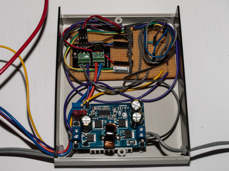
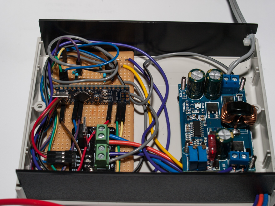
Mobile Battery Management Controller
In the image you can see (almost) everything that is in the circuit diagram. In the foreground, you see the DC/DC converter. On the vero board, you see the FET driver breakout board (left) the Arduino Micro (mid) it is sitting vertically, and finally you see the isolation diodes and voltage dividers on the right (under all the hook-up wires)
The only thing that is not in the photo is the output relay, which is outside the box.
So, there you have it! A simple, useful project to manage a battery.
It would be trivial to take the concepts presented here to manage the charge of a battery (eg, input from Solar) and auto-shut down the output or even expand on it to turn on a 240V battery charger to top-up your battery.
Please feel free to use this idea, diagram and code as the basis of your own battery manager. If you do, please do let me know that you found this useful.
I recently picked up a 70cm XVTR from http://www.transverters-store.com/432_28mhz.htm – For extra confidence, you can also purchase via their Ebay Store – http://stores.ebay.com.au/tubes-shop
Prices are the same both direct and via Ebay, Ebay for confidence if you are unsure about making a purchase directly from the Ukraine.
It arrived in about 3 weeks, not too bad at this time of the year – I bought the “kit” which includes the completed XVTR, the Attenuator/Interface/Sequencer Board, the case and a selection of connectors to get you all set up ready to use.
You will need a few additional items to put it all together!
There is no layout, nor a complete cabling diagram, you will need to use the individual wiring diagrams of the Attenuator and the XVTR boards to hook everything up. It is quite straight-forward.
The XVTR is a complete no solder board – you just need to wire up the IF input, PTT, 70cm Output and Power to the 2 4-pin headers.
The Attenuator Board, you need to solder the wires as required to interface.
In order to assemble, you are going to require some additional hardware:
Soldering Iron (duh!) – my 15/40W was perfect for the job.
(illuminated magnifying lamp – optional but makes things easy)
Screwdriver #1 philips
Drills – 3.3mm (M3 clearance)
Drills – 5mm, 6mm, 8mm,
Round file/Dremel.
First off, I selected a physical placement of the XVTR and the Attenuator boards such that:
The 432 output cable could be as short as possible
The output MOSFET was positioned such that it had maximum amount of the case near it – as per the instruction sheet
I chose to use a different switch than the supplied one, I chose a push-on push-off switch rather than the toggle, because it was a smaller hole to drill in the case for mounting.
There was nothing in the way to indicate any sort of layout of the required connections, so, it really was simply making a sensible choice while keeping all leads as short as possible. I just picked a layout that would allow a little bit of cable to enable assembly without any cable stresses during assembly.
Mark out and drill the mounting holes in the case for the 2 boards.
First off, you will need to cut 1 of the M3 nylon mounts such that it will support the XVTR board with the MOSFET mounted directly to the case.
Once done, mount the XVTR board – noting that the mounting holes are correct size to thread the M3 bolts thru – no nuts required – and significantly, the mounting hole near the output end, no nut would fit as the air-wound coil is too close!
I used a cut-off piece of the threaded M3 mounting post as the Nut for the other end of the board.
Next step was to prepare the Coaxial cables (3x) and Power (in and out) and PTT (in and out) and solder to the Attenuator board.
Next, mount the board to the case and put aside.
The ends of the case are plastic and therefore easy to drill and install the connectors and the power LED.
I used a sticky label on the inside to mark out the position of all the connections and then proceeded to drill/file (as needed) to fit the connectors to the Input end:
I positioned the connectors to align across the top of the end panel so that there would be no interference with the mounted board and still allow a sensible layout of the leads.
The layout I chose was L-R: Power (6mm hole), Power Switch (12mm hole), Power LED (5mm hole), PTT (6mm hole) and the 28Mhz IF in/out BNC (8mm/shaped hole)
I mounted all the connectors, and a little quirk indicated that the only GND input to the Attenuator board is via the Input Coax, so on the switches, I tied the GND connectors from the power, RCA(PTT) and BNC (IF in/out) together across the back of the connectors on the panel.
Once done, then I secured the end panel to the bottom of the case and hooked up all the connections.
I wired up the LED I put on the panel (with the 2.2K R) to the switch output with a bit of the heat-shrink over the lead and resistor, and the other end to the common earth bus. At this point, I applied power to verify everything.
I did note that the attenuator board does in fact have a power LED and an PTT LED on it – which is good for checking while it is all apart, but you will not see once the cover goes on!
From here, I now wired up the 2x 4-pin header connections from the Attenuator to the XVTR board. As I was dealing with power and PTT close to either an RF input or output, I opted to put a bit of heat-shrink over the soldered connection to the header pin to ensure I didn’t short out anything.
Next step was to to then mark out the 2 BNC connectors on the other end – the HF-passthru and the 70cm ports and mount them to the end.
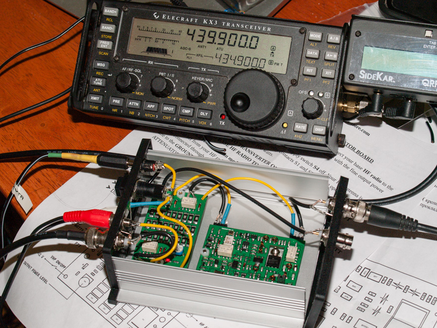
Finally, everything wired up, and hooked it all up with the KX3 configured as the IF, attached an antenna.
With a drive requirement of 1-10mW and the 30dB attenuator, I set the KX3 IF Max output to 7W (7mW after the 30dB atten). The Attenuator has 30dB in front of the variable – and I wanted to set the pot for no extra attenuation of the input.
Knowing I was in safe territory and would not exceed the 10mW Max IF input to the XVTR, I then set about setting up the atten drive. I set the KX3 to output 2W (or 2mW) and then using a nearby Handheld without an antenna on it, adjusted the pot for Maximum RX signal.
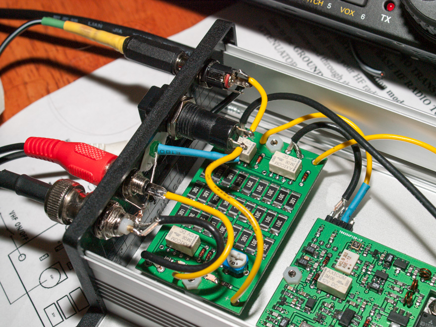
At this point, it was ready for a couple of final photos and close up the case – nothing more to do in there.
Wiring of the end panel connectorsAll hooked up and testing with the KX3 before closing up the case.
Once closed up a couple of simple on-air tests were conducted with a nearby station (Thanks Ray – going mobile about 3km away!) where we conducted a series of tests.
First off, a quick test on FM, and It delivered a similar result to the handheld running at 2-3W output.
Next, it was a quick test on SSB. It took a little bit of effort here, as at first it was around 1.3Khz high in frequency. After a few minutes of talking, the bottom of the XVTR was a bit warm, but not excessively so, I needed to adjust things a little and found that it was around 480hz high in frequency. So, it seems that there is some temperature related drift.
It did not seem to drift any more after the initial 3-5 minutes of use and warm-up, but time will tell.
I will of course note the offset and map it out and apply the required offset within the KX3 XVTR configuration so the display reads correctly.
For the cost, this is a great little afternoon project of mostly a mechanical build that will give you 70cm capabilities in an ultra-small, lightweight package.
Now, I just need to get out there and experiment with it somewhat to determine the real-world sensitivity and actually measure and plot the output power with various input power settings.
Finally a short video accessing the local repeater.