
If you are like me and drive a modern car then the simple task of powering your radio(s) in the car become somewhat of a problem. Gone are the days where it was trivial to run a cable thru the firewall and connect directly to the battery, so time to think differently.
First off I didn’t want to drill or cut holes to run cables, second, I wanted a little bit of protection. So, a little bit of thinking and it was option 2 – add a second battery specifically for the radio. This of course leads to other issues – of management (charging and not over discharging. I could have gone out and spent several hundred $ on a Battery Isolatoin solution – or I could come up with something myself.
The Problem
Now, the requirements for mobile power are reasonably simple – I run an APRS tracker in the car – so a 2m txcvr, that draws about 0.5A on Rx and around 7A on Tx for 3 seconds every 2 minutes. The other requirement is the HF/VHF/UHF mobile txcvr (IC-7100). The ‘7100 draws around 1A on Rx and up to 22A on Tx (but more like 10A on VHF/UHF).
First off – the good old 12V plug (cigarette socket) is not so great – in the car, with all sorts of unknown management, we discovered that the voltage varied between about 10.5V and 14.2V when the car was on and running and often drops down to sub 10 when drawing more than about 6 or 7A or so. This made the car provided DC useless!
The Solution
Time to look at how to use this unreliable power to keep a 2nd battery charged, whilst also not allowing the 2nd battery to over-discharge.
So, a simple plan was put in place to put together a suitable charger and battery manager.
The solution in the end was quite simple (and came out a lot cheaper than a commercial solution.
I knocked up a fairly simple, straight forward circuit and sourced all the components/building blocks that I needed.
The Components
- Arduno Micro controller – I used a Nano (but a Pro Mini would also be suitable)
- 40A 12V Automobile SPDT relay – I got one in a holder with leads
- DC Step Up/Step down converter with CC/CV output
- Mosfet on a breakout board.
- 4x Diodes
- 2x 15k and 2 6k8 resistors
- A piece of vero board
- Hookup wire and various connectors.
I sourced most of these items from Ebay, my junk box or a local retailer for literally a few $ each.
I chose to put an Arduino Micro to the (simple) task of managing my battery – more on this shortly.
I found a suitable DC/DC converter that met my needed criteria: It had to have an input voltage range of at least 8-16V and output of 10-15V at 5A. I found one on Ebay was 1.5-20V input and 5-32V output at 5A. It had both a CV and CC adjustments – so It meant that I could set the output to 14V and limit the current to 5A.
The relay was similarly sourced from Ebay, On testing it, I found that the relay I obtained required about 140ma to operate it. So that would require a suitable transistor/FET so that the Arduino micro could drive it. Again, off to Ebay was the easiest solution was a simple break out board with a MOSFET. I found one for about $1 that had an IRF520 device. A quick look at the spec sheet and it is a massive over-kill for this task, but given the $ and the convenience of already being on a breakout board, ready to hook up I grabbed a couple.
Now the only part I really needed to think about, and then it was not even a lot – was monitoring the input voltage, battery voltage and powering the Arduino.
Monitoring battery voltage is trivial – just a simple voltage divider for input to one of the ADC Inputs.
Powering the Arduino – well this is where I get a bit creative – and fell back to using a handful diodes to provide multiple DC sources to power the micro. This will make sense why I did it the way I did when we get to the code for the micro. Given that I only needed to isolate and supply less than 10ma I went with some 1N4148’s that I had.
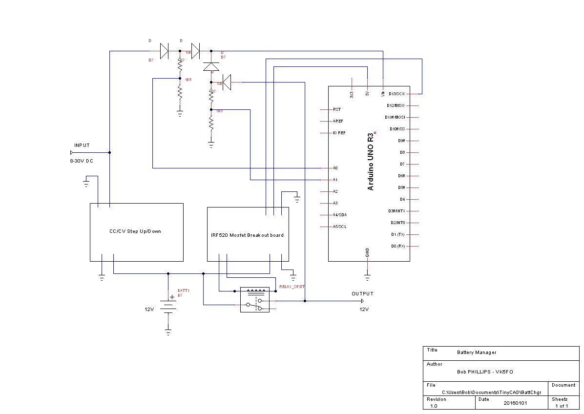
Circuit Operation
It really is quite simple when you look at it.
Input power to the DC/DC converter and it will charge the battery. This input comes from the car – yep that horrid 12V socket.
We also take the input and feed it thru a diode, to isolate it for a voltage divider for monitoring the input voltage on A0 of the Micro, then thru another diode to the Vcc pin on the Arduino. The Nano has an on-board 5V regulator and is quite OK with up to about 15V input.
When the Arduino has power, it can start running the code.
The first thing that the code does is to drive pin 13 high – which goes to the MOSFET, and in turn enables the relay.
Once the relay is on, we take some of the output, and again with our diode, we isolate a voltage divider to feed A1 of the Micro, then thru another diode to the Vcc pin.
Now this might seem a bit counter-intuitive – but it is not! We have supplied 2 possible power sources to the micro – which is monitoring and managing our 2nd battery, and more on that when we look at the code.
The Code
I decided that whenever there is an input voltage (ie the car is running) that I would turn on my 2nd battery, and it would remain on for 7 minutes after stopping the car as long as the battery voltage was over 12.05V
/*
* Battery Charge Controller
*
* Bob P 20160101
*
* V 1.0
*
* Monitor Charge/Input voltage
*
* Monitor Battery output voltage
*
* Turn off output voltage if:
* 1. Charge voltage off for more than xxx minutes
* 2. Charge voltage off and bettery voltage less than xx.xxV
*/// Init all variables
int CHGvolt = A0; // A0 charge voltage sensor
int Battvolt = A1; // A1 battery votage sensor
float CHGread = 0; // Variable to store chg voltage
float Battread = 0; // Variable to store Battery votage
float volts; // Variable to store voltage Divider value
long ShutTmr = 7; // Minutes until shut down when loss of Charge voltage
float LowVoltCut = 12.05; // Battery Low voltage cut-off
long UntilShut = 0 ; // Count down timer until we shut downbool StartShut = false ; // Start the shutdown timer
void setup() {
// set up voltage divider values for ease of maths
volts = (float)6800 / (6800 + 15000); // gnd, 6.8k, measure, 15K, +vccpinMode(13, OUTPUT); // output relay
digitalWrite(13, HIGH); // turn on output relayUntilShut = ( ShutTmr * 60 * 1000 );
// Serial for debug only // comment out when in use
Serial.begin(9600);
}void loop() {
// put your main code here, to run repeatedly:// See if shut down timer has expired
if ( millis() > UntilShut ) {
digitalWrite(13, LOW); // Time out has expred, shut down
}delay(5000); // let everything settle before we do anything
// read the CHG Voltage, convert to Actual Voltage
CHGread = analogRead(CHGvolt);
CHGread = (CHGread / 1024) * 5 ; // 10 bit DAC with 5V reference
CHGread = (CHGread / volts) + 0.8 ; // Actual input voltage, including 0.8v diode drop
// read the Batt Voltage, convert to Actual Voltage
Battread = analogRead(Battvolt);
Battread = (Battread / 1024) * 5 ; // 10 bit DAC with 5V reference
Battread = (Battread / volts) + 0.2; // Actual Battery voltage, including shottkey in relay
// OK, lets look and see if we have a charge voltage
if (CHGread < 8.00 ) {
// we have lost input/charge voltage
// If we have not already commenced a shutdown, time to do so
if (!StartShut) {
//Serial.print( “starting shutdown.. “);
StartShut = !StartShut;
UntilShut = ( ( ShutTmr * 60 * 1000 ) + millis() );
}
// Now we look at the otput voltage and kill it if the voltage is too low
if ( Battread < LowVoltCut ) {
digitalWrite(13, LOW); // Kill the output
}} else {
// So, our Charge voltage is good, we reset shut down time and cancel the sut down
if (StartShut != 0 ) {
StartShut = !StartShut ;
//Serial.print(” Shutdown Cancelled ” );
}
// reset our shut down timer
UntilShut = ( ( ShutTmr * 60 * 1000 ) + millis() );
//re-enable the output – if it was shut off due to low voltage before timer expired
if ( digitalRead(13) == LOW) {
digitalWrite(13, HIGH);
}
}/*
* Debug print block
//Serial for debug only // comment out when in use
Serial.print(millis());
Serial.print(” Timer “);
Serial.print(UntilShut);
Serial.print(” milliseconds until power down “);
Serial.print(“Charge Input Voltage: “);
Serial.print(CHGread); // print the charge input voltage
Serial.print(” Battery Voltage: “);
Serial.println(Battread); // print and end line the battery voltage
*/}
You can download the BattChgr sketch which is correctly indented.
Now we are not really doing anything fancy here – it is all very basic stuff for anyone who has looked at programming an Arduino
We set up the variables we are going to use,
The 2 important ones are ShutTmr and LowVoltCut. This is where we configure our battery management.
I chose a 7 minute shut down timer and a lo w voltage cut-out of 12.05 Volts – which I will explain as we go thru the code.
Then in the setup() function we turn on the relay – pin13 high and do a simple calculation that we will use later on.
Into the Loop()
We check to see if the timer to shut
We then take a nap for 5 seconds before we look at our input voltage (A0) and Battery Voltage (A1).
Once we check the voltages, we then move into the logic and check we have an input voltage,
If the input voltage is less than 8 Volts we assume we are no longer charging and take some actions:
- We check if we have already commenced a shut down, and if not set the shut down flag to on and set the shut down timer to the configured time:
- We check the output voltage and if we are below our low voltage cut-off we turn it off
What is interesting to note here, is that if we have no input voltage, from the car, then we turn off the output relay, and the Arduino will shut down until we turn on the car again.
If the Input voltage is good, we check if the Shut down flag was previously set, and if it was, we reset it, cancelling a shut down. and also reset the shut down counters again.
The final bit of code you will see is commented out – I tend to use serial print to display the value of variables when debugging the code, comment it out once everything is working!
Could I have done this differently – sure, could I further improve and simplify this code – absolutely! Does it work exactly as I want it to – Sure does, so for now, I have archived it away along with the diagram should I need to go back and make another one for the next car or maintain this should I need to.
The final steps were to put it all into a box, hook it up and put it in the car.
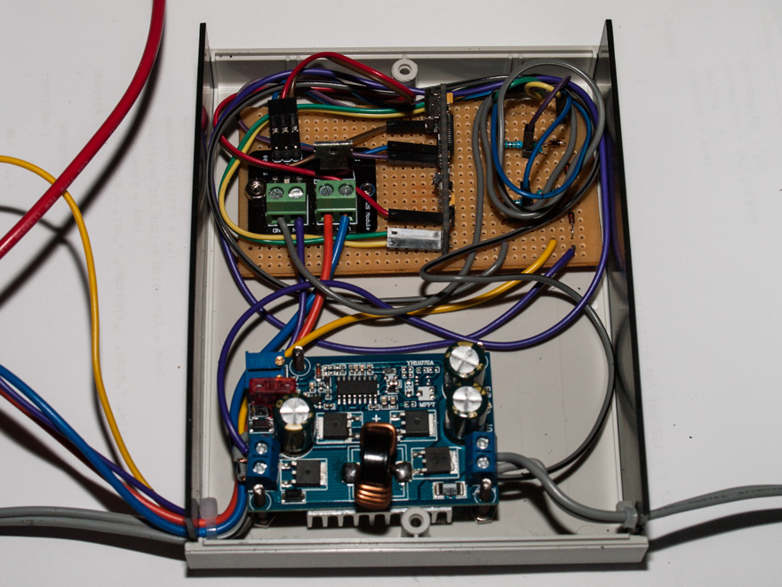
In the image you can see (almost) everything that is in the circuit diagram. In the foreground, you see the DC/DC converter. On the vero board, you see the FET driver breakout board (left) the Arduino Micro (mid) it is sitting vertically, and finally you see the isolation diodes and voltage dividers on the right (under all the hook-up wires)
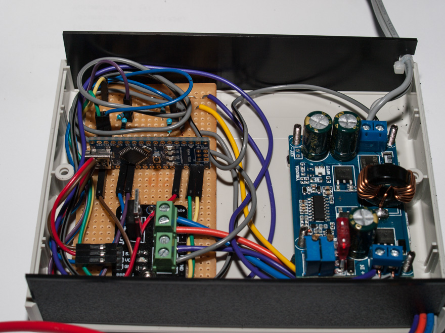
The only thing that is not in the photo is the output relay, which is outside the box.
So, there you have it! A simple, useful project to manage a battery.
It would be trivial to take the concepts presented here to manage the charge of a battery (eg, input from Solar) and auto-shut down the output or even expand on it to turn on a 240V battery charger to top-up your battery.
Please feel free to use this idea, diagram and code as the basis of your own battery manager. If you do, please do let me know that you found this useful.