Loops, Verticals and Inverted V’s

Over the last few days I had the opportunity to borrow a 40m Transmitting Magnetic Loop Antenna with a big thanks from Steve – VK5SFA for the loan of his 40m loop so I could conduct some comparisons.

We were at the shack in PF95wu where I have the GAP Challenger Vertical and where I could put up my portable 40m Inverted V antenna.
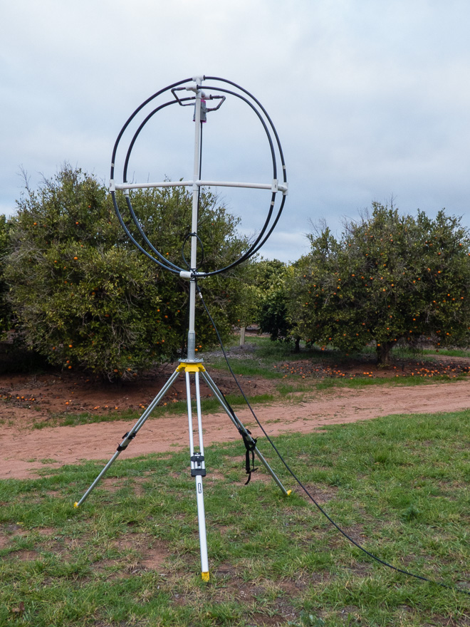
VK5SFA 40M loop
VK5SFA 40M loop

The loop is physically quite small  at only about 1.6m in diameter – and as you can see it was mounted on a tripod with the bottom only 1.8m off the ground, and as far away as my coax would allow from the shack – which was about 10 or 12 Metres.
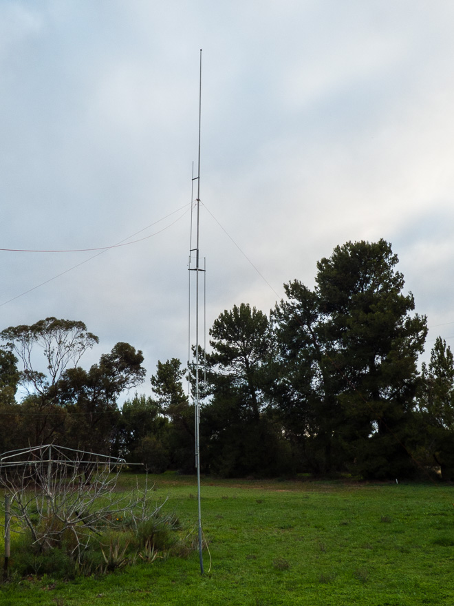
Gap Challenger Vertical 80-2m

The Gap Challenger, which has been put to use as the primary RX antenna for the KiwiSDR – was one of the comparison antenna’s used over the few days.

For the TX experiments I used the KX3 and HR-50 Amp and was transmitting at between 40 and 55 Watts of power.

Observations – the Loop

The bandwidth of the loop was quite pronounced – tune the loop, tune the RX across the band and it was pretty obvious – about 40khz wide.

TX – well, it was nowhere near 40Khz wide – more like about 12 or 13khz 1.5:1 VSWR bandwidth.

The first night, we had a bit of rain earlier and the ground was a little damp.  We found it impossible to actually tune the loop – best we could get was about 4:1 VSWR on TX.    The next night it was much better!

Tuning – well touchy is an understatement!  The tuning is manually done via an insulated rod – and 1/4 of a turn was like 40khz!  It was a case of tuning for maximum RX noise, then some careful fine-tweaking to get it there.

RX Bandwidth

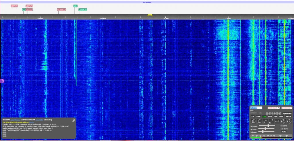
The Loop was tuned to 7.140 and plugged into the SDR
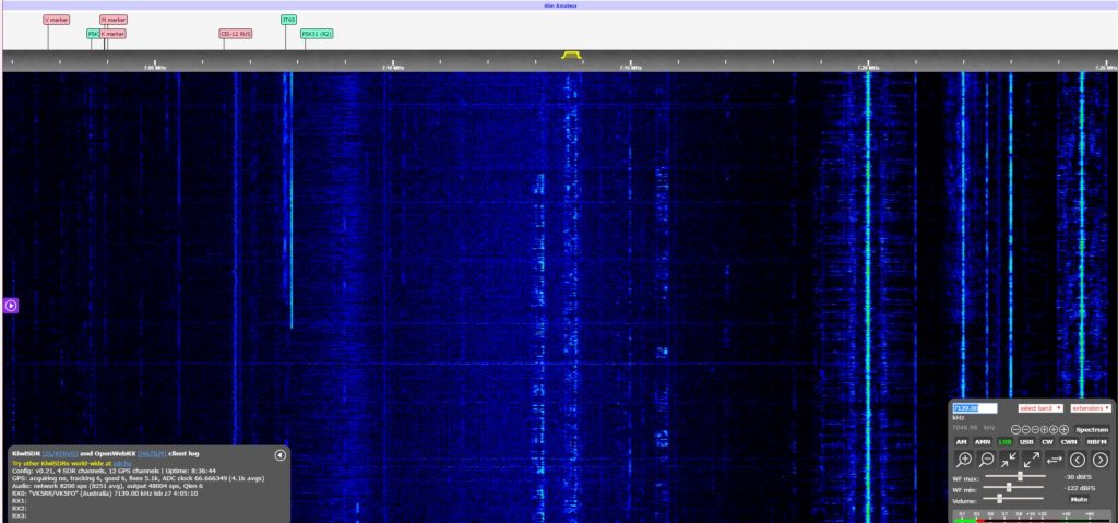
40M loop on SDR
40M loop on SDR

Without changing any settings on the SDR, the Vertical was plugged back in.

40m-vertical

IT is pretty obvious as to the RX bandwidth and how sharp it drops off away from the centre frequency.

Click on both Images to see full sized.

Usage

I made use of the Loop to talk during the day – local, single-hop contacts (VK2, VK3, VK4) – and when 40m is open, it is open – 59 contacts – no real difference between any antenna.  DX – I did have a couple of contacts to the West-Coast US using the Loop – and got respectable reports back based on my 50W!

The Loop has  2 large lobes, and quite a deep, but fairly narrow null on each side.  The null is about 50-60 degrees and 2 S-points – or probably around the 12db  mark (give or take).  We did have a little bit of local noise, and rotating the loop we observed the noise drop right off to S1-2 when nulling the noise.

Side by side, with the Vertical – RX was on par, and TX was much better – just because there is a slight directivity associated with the loop .

Side by side with the Inverted V – well this was much more interesting – The Inverted V was only 8m high with each end about 2m off the ground.

The Inverted V was 2-3 S-points noisier than the Loop, but also 1 S-point stronger on the signals.  With an  S6 noise and  S9 Signal for the VK contacts, versus’s the loop, with an S3-4 noise and an S8 signal.

It clearly had at least 10db better signal to noise versus’s the Inverted V – and well, hands down beat the Vertical on TX!

The far stations reported slightly stronger signals on the Inverted V, but I don’t hold much faith in that as there was heavy QSB – I would call it a tie.

Conclusions

I would conclude that it is about on par with a dipole in typical performance – but has a considerably smaller footprint!  I was actually not expecting that the performance to be as close to the Dipole/Inverted V as it actually was – remarkable considering that you only need a very small space to have the equivalent of a rotatable dipole!

For the Amateur who is space-challenged or has a lot of noise, then yes, a loop is certainly worth considering for the low bands.

As we have the Loop for a couple more days, we will set it up in a typical urban lot – where we simply cannot use 40m as it is always S9+ noise  and make some observations as to how effective it is in a much noisier environment.

Remote Rx

Our previous JT-65 experiments came to an end when we needed the Antenna at our remote site for something new.

A few month’s ago, we jumped on-board with the KiwiSDR  and have been waiting for the project to come to fruition.

Kiwi SDR Kickstarter

Kiwi SDR Website

Other web SDR’s

So, after seeing a few Kickstarter updates and knowing that there were a handful of beta/test sites out there I decided to make contact with the Project Owner – John, ZL/KF6VO and put together a “proposal” to offer up the site as another beta test site.

Well, as luck would have it, John was happy to work with us for a couple of reasons – He had just 1 of the 10 boards left from his initial beta production run and he did not have a beta test site in VK.

After discussing details for a little while John sent the KiwiSDR and we have installed it onto the Gap Vertical Antenna in the Riverland.

Since it has been installed, we have found that the RX to be quite sensitive – quite surprising really!  The software is really quite easy to use as well.

It was a real eye-opener to “see” the whole 30Mhz of spectrum in the band scope display and realize just how much local noise there is at our site!

We know that there are still some software issues and within 24 hours of installation a further software bug was found and the auto-update rolled out the new version of software.

We are still waiting for a nice and quiet (rf-wise) linear power supply to arrive, and have it running with a fairly noisy switched-mode supply. As soon as we can this will get swapped out and hopefully improve things even more.

The Rx front-end is very sensitive to local noise – and we found that on power-up we had a very high noise floor.   We found that the noise was simply that the Ethernet cable crossed over the Antenna coax cable – and it introduced over 40db of noise, so some careful re-routing of cables was done and we saw massive improvements.

Yes,  there does need to be careful consideration of the installation and we could probably do a lot better than the simple protective case the SDR is in – we will probably put it into a decent metal case that is earthed to further reduce any local noise getting into the front-end in the near future.

Our previous experiments with JT65 had already proven to us the advantages to be had with running a remote RX site, and having the whole HF band available with the really simple and powerful interface has been great!

At the price-point, it is a great SDR – and much better than a simple panadaptor that only shows a single band – It is going to be one of those “Must Haves” for your Contest Station!

A little about the interface itself – Very easy to use – a simple point and click – select mode, select zoom on band display, enable/disable spectrum display, drag the audio passband – a continuously variable filter set the low and high cut frequencies to suit. Easy to adjust the Waterfall min and max sensitivity – once you set it for the band/noise floor it is really easy to “see” what is happening.

Whilst there is no noise filter, I have found that small adjustments to the audio passband can make a big difference.

There are now about 10 of the KiwiSDR’s around the world – so have a play  – you will probably go off and order one for yourself!  I will probably be getting a 2nd one after seeing how good this is!

… and just in case you have not already found it –

Have a listen on My KiwiSDR

Comparisions

Over the last several weeks we have been running an experiment – an experiment that is all about doing the same* (similar) thing at different locations.

We are fortunate enough to have more than a single QTH where we can set up an amateur station, so we have done so.

Station 1

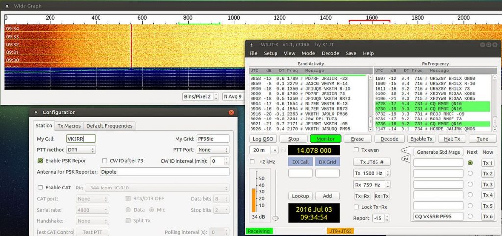
We set up Station 1 at our Main home QTH in the City – in PF95ie

The station consists of the following

  • Kenwood TS-2000 TXcvr
  • Dipole at 11m high (running North/South)
  • Pine64 Running Debian Mint and the current version of WSJT-X into a USB sound card.

Station1

Station 2

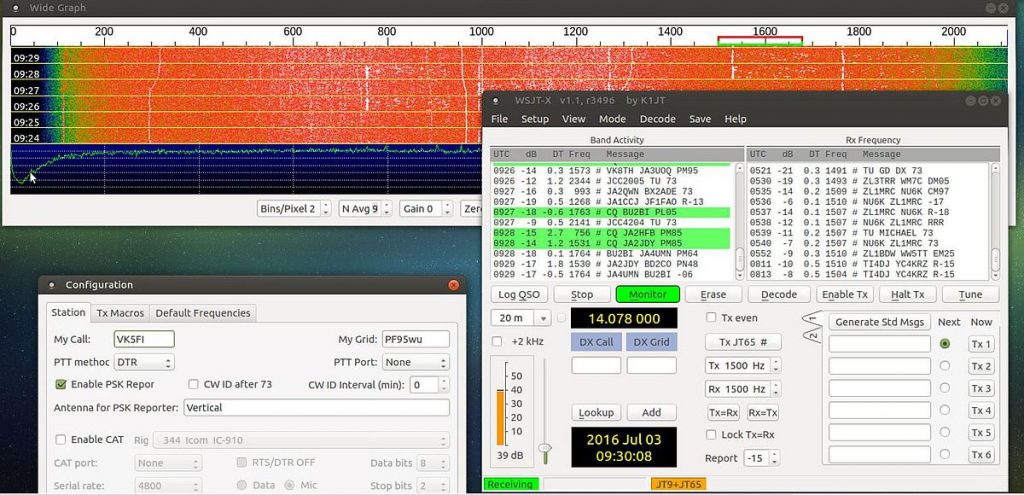
We set up Station 2 at our shack in the Riverland, approx 160km away in PF95wu  This is a semi-rural location with less than 50 houses within 1km, but in an active irrigation farming area (think pumps switching all the time)

The station consists of the following

  • Icom IC-706 (yep the 20+ year old original version)
  • GAP Antenna Challenger DX Vertical
  • Pine64 Running Debian Mint and the current version of WSJT-X into a USB sound card.

Station 2

As you can see both stations are very modest – and what I would call Atypical of what someone might have installed.  There is not a lot of differences between them – but, granted, there are differences.

We chose to do this experiment with JT65 simply because of the ease of setting it all up and having it automatically report the results.  We could have probably done the same and set up a similar experiment with WSPR, but chose JT65 as you can actually have a “QSO” using this mode.

We wanted to set up the stations to reflect what would be reasonably easy for almost anyone to set up and have working with a minimum of fuss – just using whatever antenna you have and whatever TXCVR you have as well.  Ah yeah, also, to put a couple of VK5 Callsigns in the reporter list so the rest of the world knows we exist 🙂

As a point of interest, we have had the Vertical antenna and the same dipole installed at Station 1 for several years, and never really had much luck with any contacts on the vertical – it was always a lot noisier in the city than the dipole.  The only advantage it gave us was it is no tune, all band.

The Experiment

We set up both stations to operate 24/7 on 20m listening to JT65 segment of the band on 14.075USB, both Stations were tuned to show the same signals in the waterfall – so as not to distort what is being heard by each station.  Both stations have the pre-amp on, bandpass filters set to 3khz, no noise blanking or filtering enabled.

Both stations are set up to report to PSK reporter so we could collect the data and analyse the results.

Station 1 is set up using the callsign VK5RR and station 2 is set up using the callsign VK5FI and they have both been running for a few weeks now,   It did take a couple of weeks to get the 2 stations set up so that they were stable and pretty much on the same frequency

While we were setting up the baseline so we could see some results we were simply monitoring pskreporter and making a mental note of the results.   Once we got to a point of seeing consistent results from both stations with them both up and reporting for more than 2 weeks, we have started grabbing some stats from PSK reporter and assembling them over the last few days.

The Results

Well, the experiment is ongoing, so results are simply a snapshot in time of our observations over the last few days.

As this experiment is ongoing, you can view the results in real-time yourself. follow the 2 links below, select Band, 20m, Mode JT and the desired time window.

Station 1

Station 2 

Station 1
DateTime UTC1 Hr2 Hr3 Hr6 HrWeek
30/06/20162130000133
01/07/2016013069151634
030038111834
0430611122534
120000195035
02/07/20160000614283029
0200915173730
0620515162729
12301142329
13302221729
0130710202830
06301117233131
0930621244532
Station 2
DateTime UTC1 Hr2 Hr3 Hr6 HrWeek
30/06/20162130610164076
01/07/201601301949699976
030021355911377
043036476111677
1200003510877
02/07/2016000035547811574
020021436911876
062030517311176
1230612178876
13302627288776
01302242647880
0630559111014481
093021537916882

Conclusions

Strictly speaking, since the experiments is still ongoing there are none – but simply some observations of the results that we are seeing.

  • The 20m band (winter propagation) does shut down for significant portions of the day.
  • There is significant differences in the observed results for each station
  • Station 2 has much better “ears” than Station 1 – considering that our usage of the Vertical has been disappointing over the  last several years
  • City locations with the inherent HF noise floor (which is evident in the images above) are not such a good place if you are wanting to use HF.
  • It is interesting to observe and note what time of day favours what part of the world – it is pretty easy to see when the band is opened to where in the world.

So, where to from here, that is easy, the next step will be to put up a dipole at station 2 and make observations over another week or 2 and see if this has a significant impact on what is being heard.

One thing for sure, we really need to spend a bit more time on our remote station and HF might just become one of those things that is not beyond reach.