
VK5RWR – Riverland West Repeater
Myself, VK5FO and VK5RR have completed the build on a repeater in the Riverland – approximately 10km west of Waikerie.
As of June 2022 the Repeater is Operational.
APRS Digi and I-Gate – 145.175 (Operational) 60W
VHF Analogue Repeater 146.750 / 146.150 (-0.6Mhz) (Operational) 91.5hz CTCSS – 50W – linked to the Adelaide Repeater Network
UHF C4FM Repeater 438.750 / 431.750 (-7Mhz) (Operational) 50W
The UHF repeater is a DR2-XE, running an up to date firmware. This repeater has several enhancements over the earlier DR2-X and the DR1 range, including better thermal protection. If the repeater gets too hot, it will throttle the TX power down to 20W, then even 5W in order to minimize the risk of thermal failure.
The UHF repeater is running in AMS – Automatic Mode Selection – which means it will detect if you are using Analogue or C4FM (Digital) to give the maximum flexibility for users.
When transmitting analogue there is a 91.5hz CTCSS tone on TX so that you do not hear the digital tones when the repeater is running C4FM.
The repeater is running in Wires-X mode via a HRI-200 interface and it is configured to default to the “Adelaide 10G” (69159) Room. C4FM users are able to disconnect and dial up to any of the worldwide Wires-X rooms, and after 20 minutes of inactivity the repeater will disconnect and re-connect back to “Adelaide 10G”
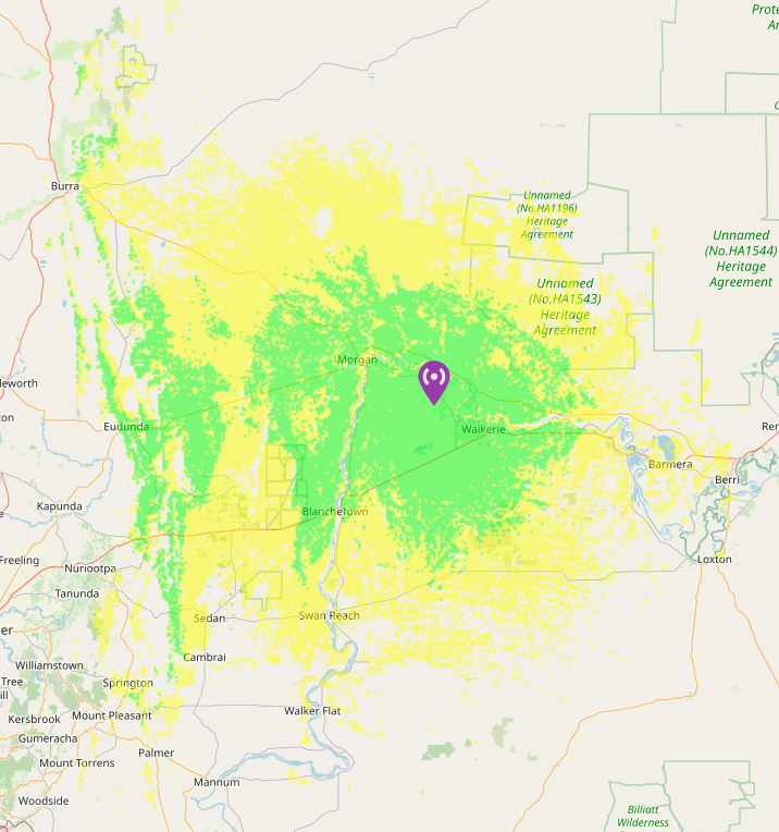
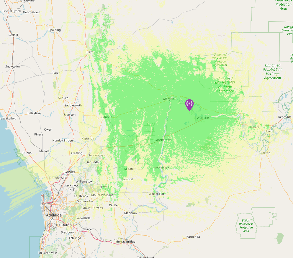
These coverage maps are relatively accurate and the green area is high signal, where the yellow is lower signal, but should be useable from a 50W mobile with a roof-mounted antenna.
Our whole aim of building this site was to compliment existing repeaters and fill in a hole. To that end, the coverage on the Eastern side of the range, across the Western Riverland area, that will have a slight overlap with the Existing VK5RLD (Moorook) Repeater.
To that end, our objectives have been met.
The Astute may have noticed that the VHF frequency is the same as VK5ROC – Near Port Lincoln. In the planning phase this was given careful consideration.
Reality is that the 2 repeaters are around 370km apart and the Mt Lofty ranges is in between them. VK5RWR is located at only a very moderate elevation and not on a hilltop. Yes, in summer it may be possible to be within the access area of both from the top of the range, the likelihood of interference is minimal.
We put together a few updates as we were working on the site and build along the way.
Update – 06-Oct-21
We have completed the earth works and are now almost ready for the concrete for the tower and shed to be laid.
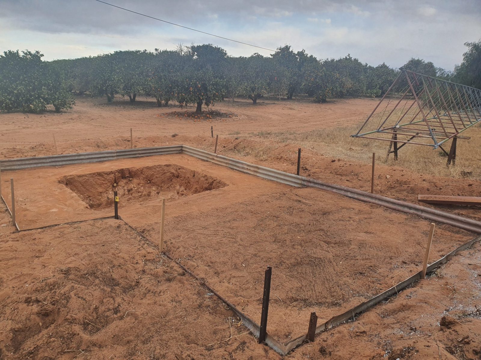
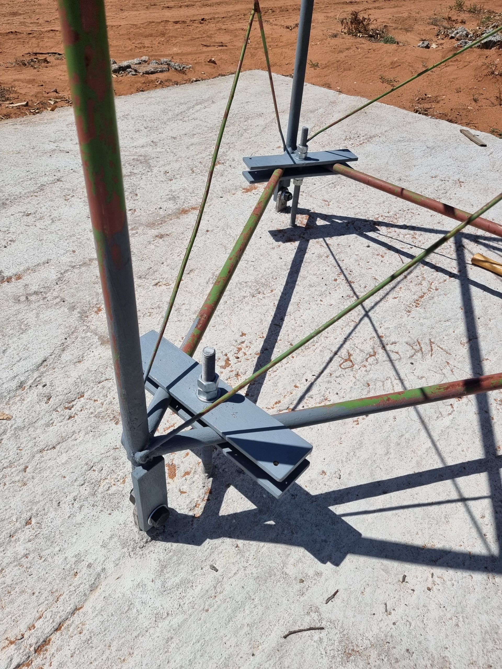
The ground is sandy with limestone, we could not go (very) deep, so we had to go wide as well. The tower will sit over a 2x2x1M “hole” with a 4x4x.25M Slab over the top of it, with an additional slab off the side where the shed will go. The total mass will ensure that the Tower will be stable! The Tower is 60 foot (19M) and will have the antenna’s on a 4M pole in the top – For a height of nearly 23M for the UHF Antenna array and just over 21M for the primary VHF Antenna Array.
Update – 31-Oct-21
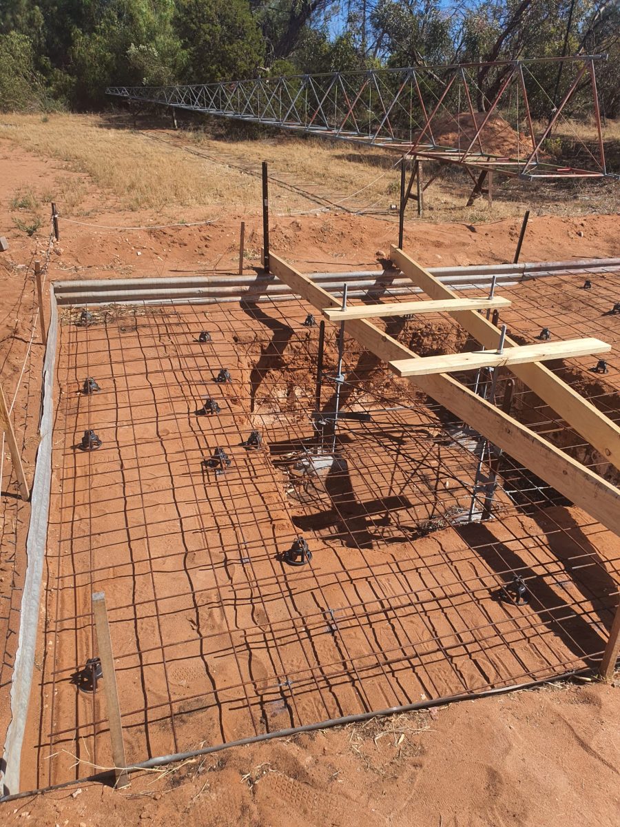
All meshed up and ready for the pour on the first weekend of Nov 21
Update – 6-Nov-21
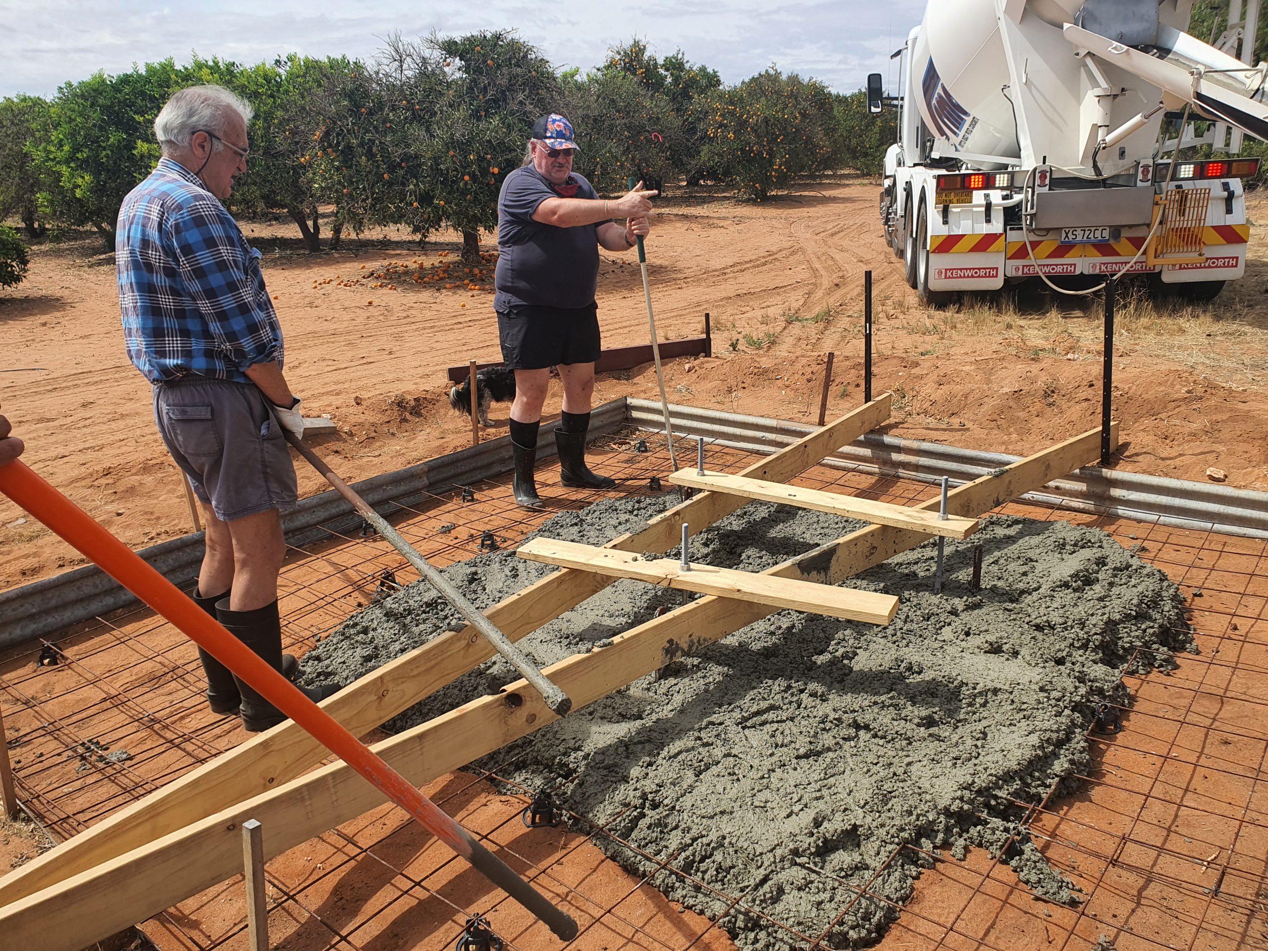
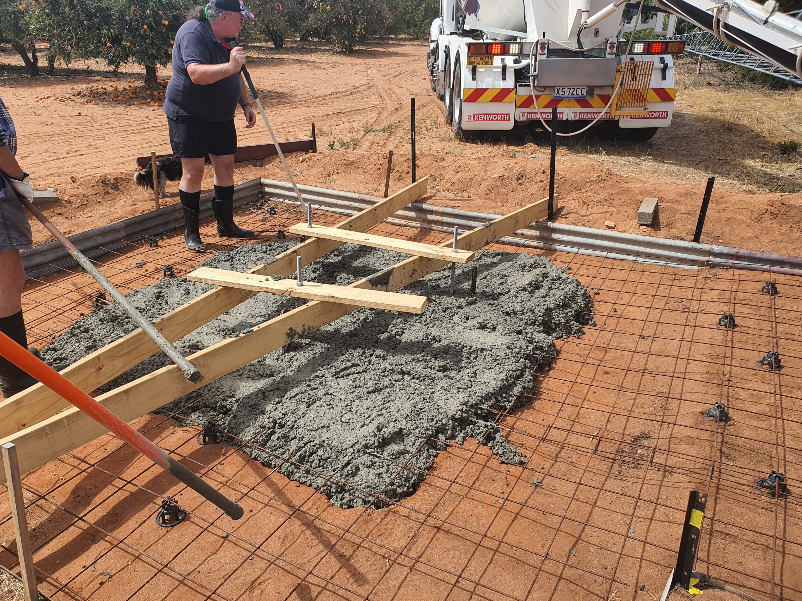
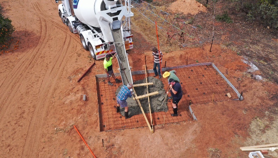
The Truck arrived, and let the pour commence.
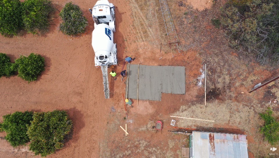
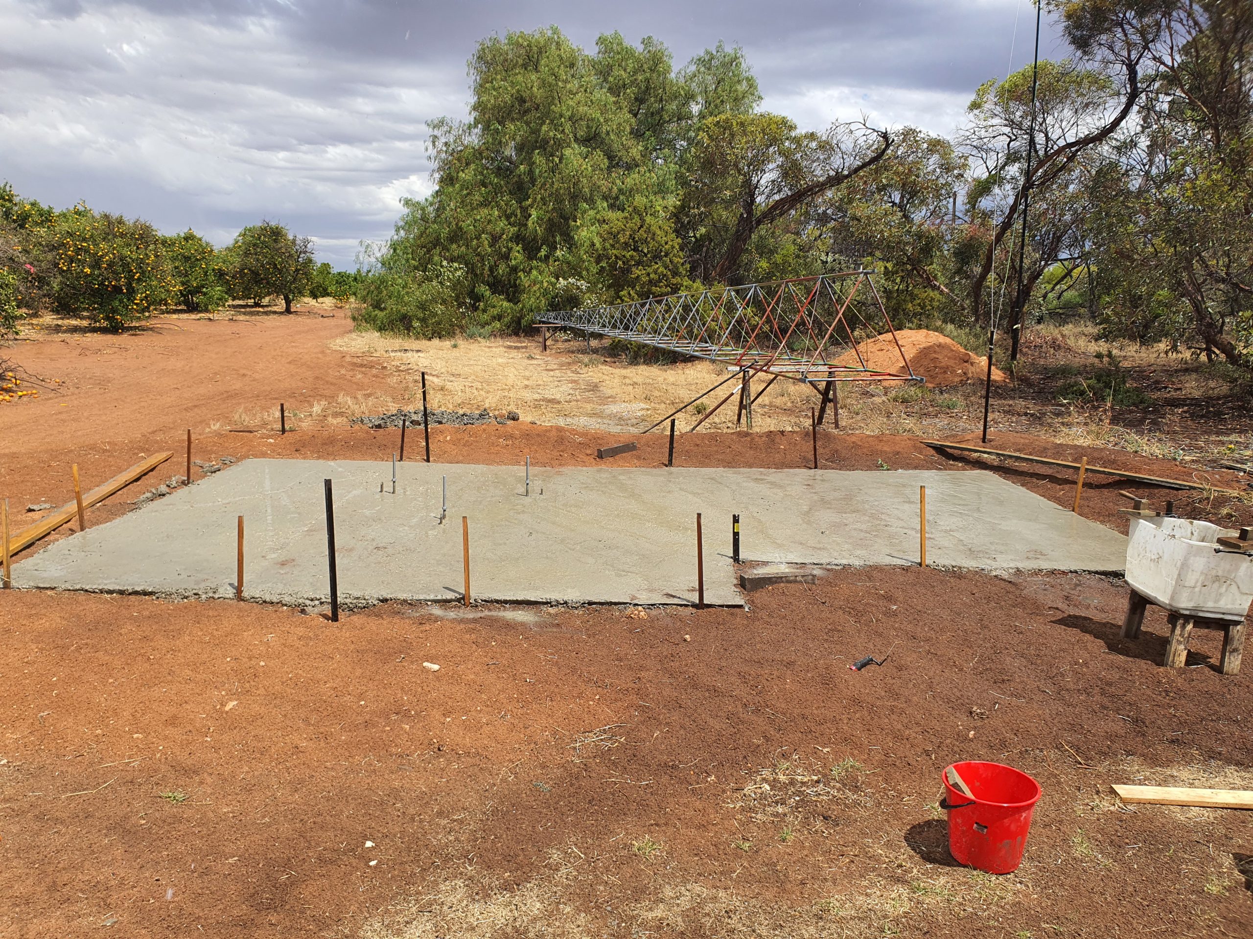
A few hours later, the truck dropped the 8.2M3 of concrete, we leveled it up (well, mostly) and next steps will be to hurry up and wait for 3 or 4 weeks, then build the shed, and dress the tower ready for it to go from horizontal to vertical.
A huge thanks to the few who were able to come along and assist with to work today, it was most appreciated.
Update – 14-Jan-22
Best laid plans, get delayed.
A few issues with connectors – and Andrews LDF5-50 connectors DO NOT fit on AVA5-50. Anyway, past that and the cables have connectors, the antennas are mounted to the tower.
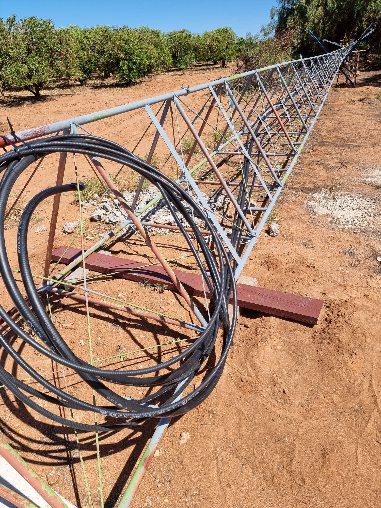 2 runs of LDF4-50 for the VHF Tx and Rx arrays, and the AVA5-50 run for the UHF array.
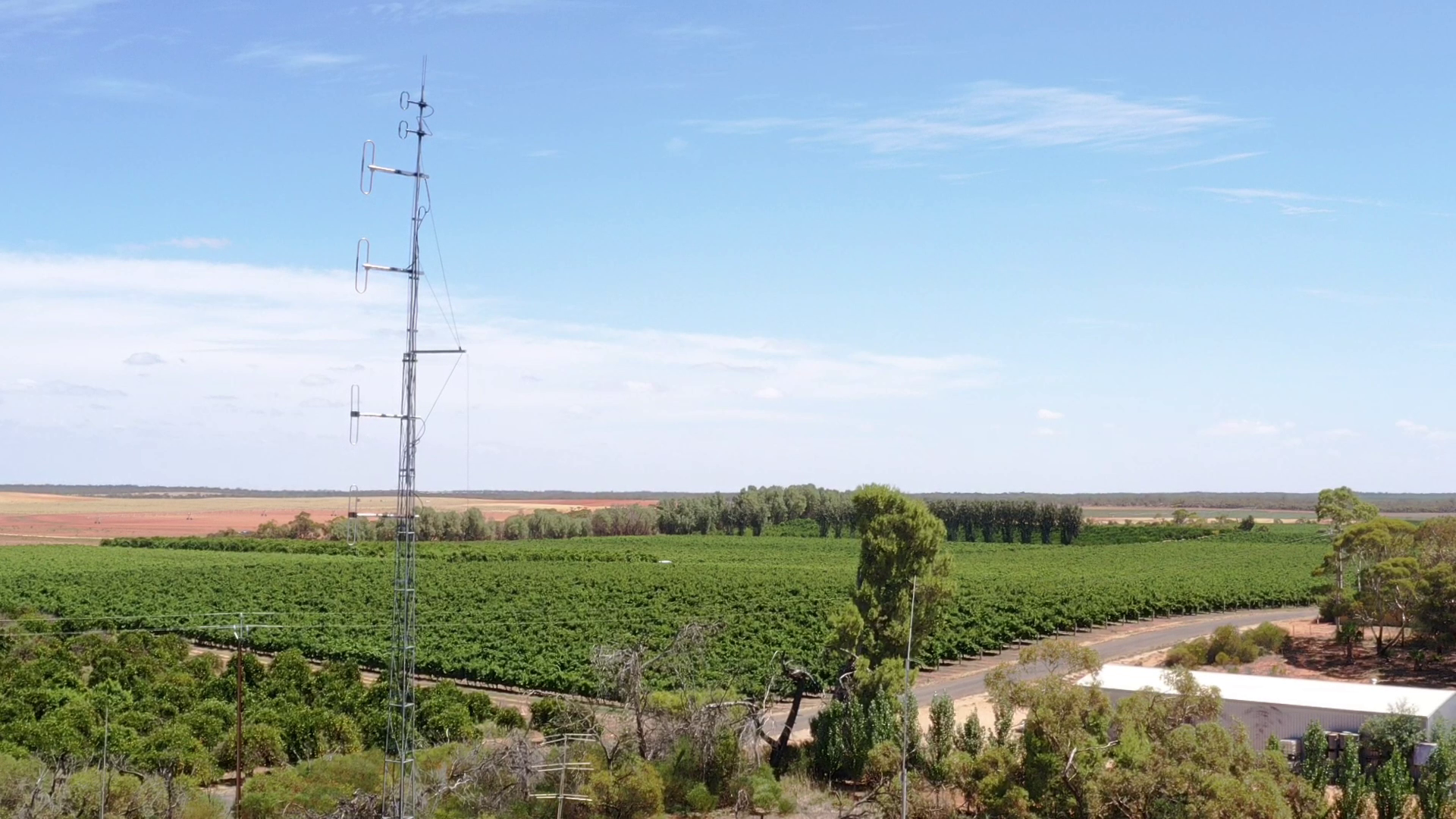
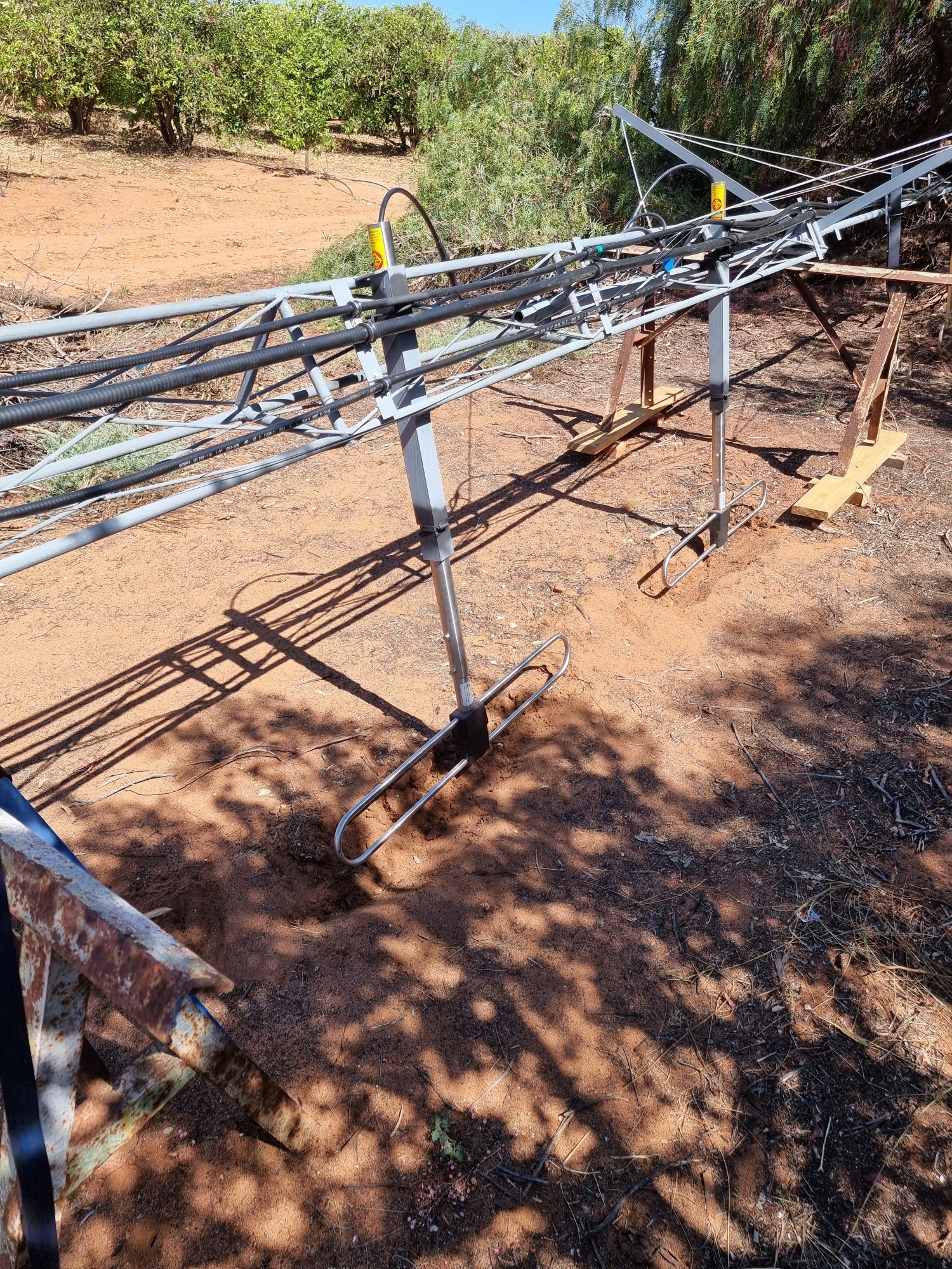 The Tx array – pair of folded dipoles
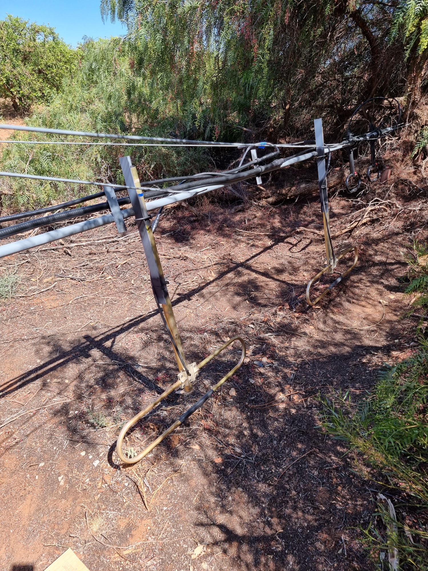 The Rx array, again a pair of folded dipoles.
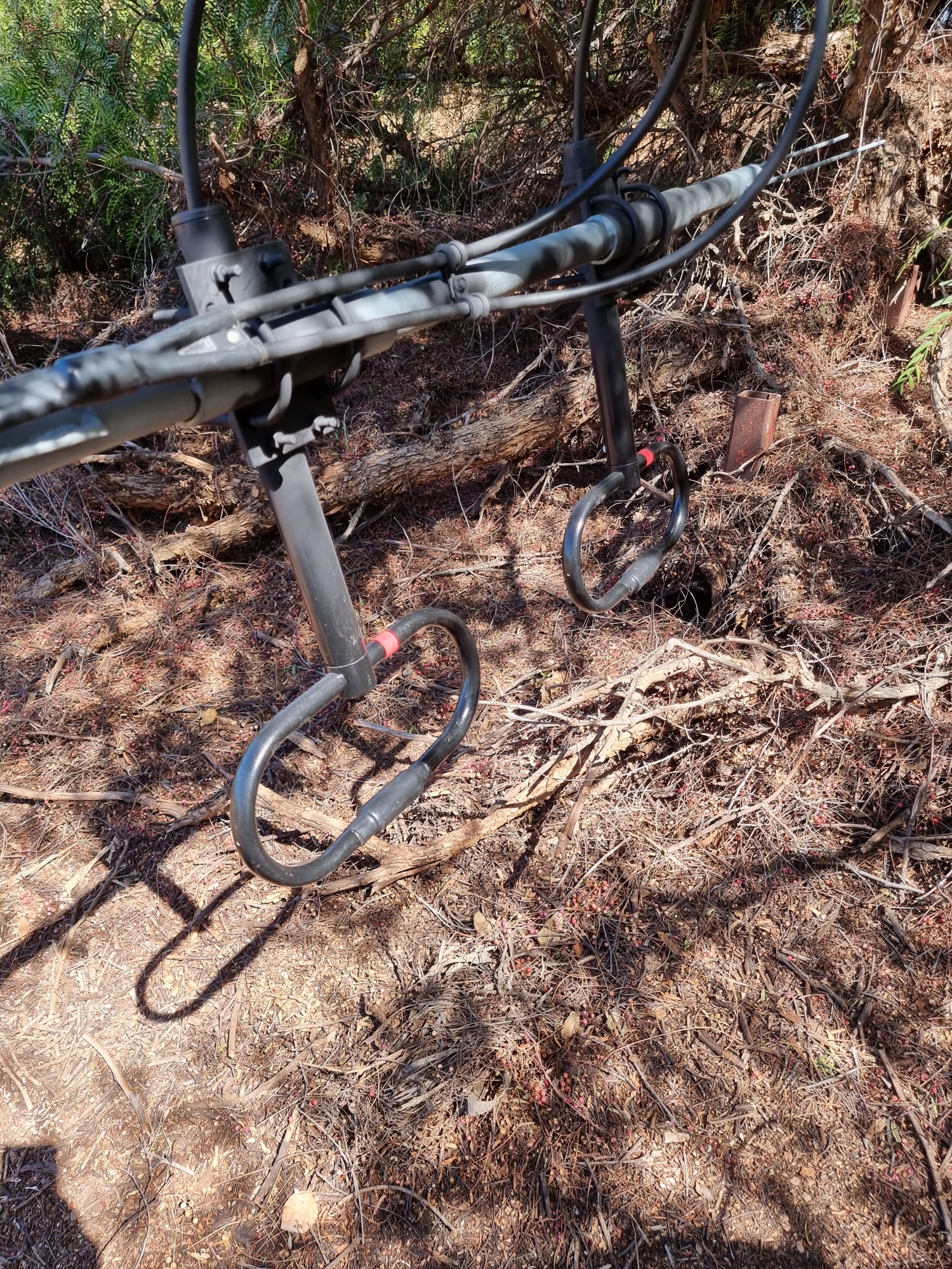 The UHF array, yes you guessed it another pair of folded dipoles.
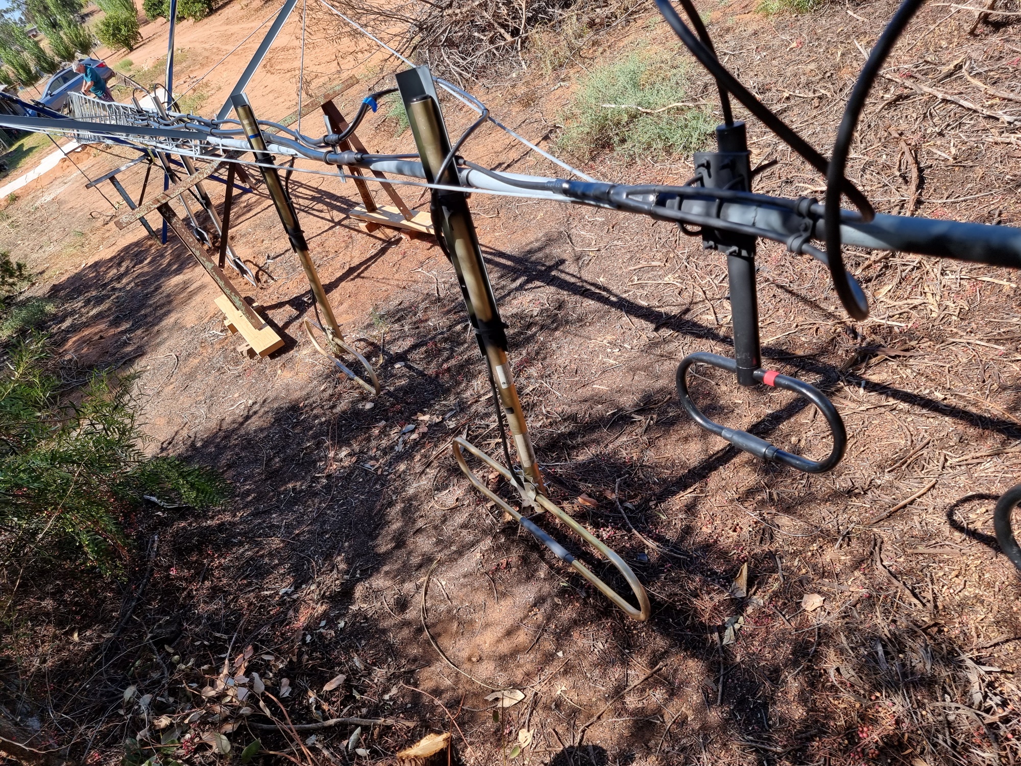 You get a sense of the size, 23M down to the bottom of the tower.
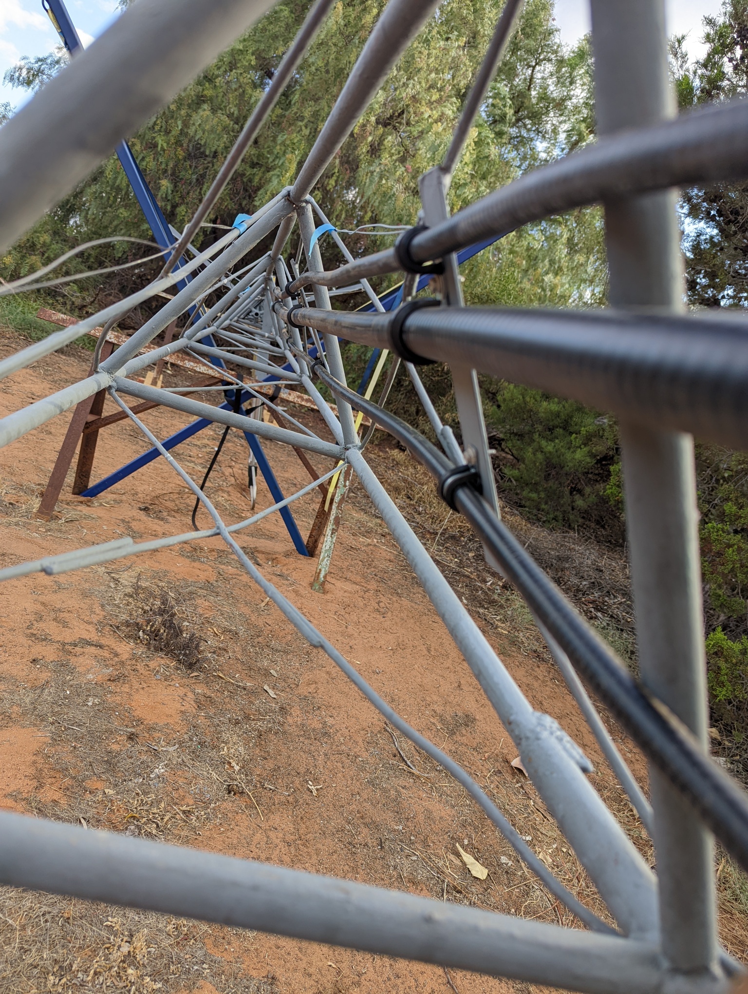 Yes, it takes a long time to mount the cables and dress the tower – all up it was almost a week’s worth of effort
Now we are again at the hurry up and wait stage, we are waiting for the crane to come along and stand it all up – stay tuned it is all scheduled.
Update – 09-Feb-22
Well, finally it is crane day – beware – tower porn follows 🙂
 Ready to stand up
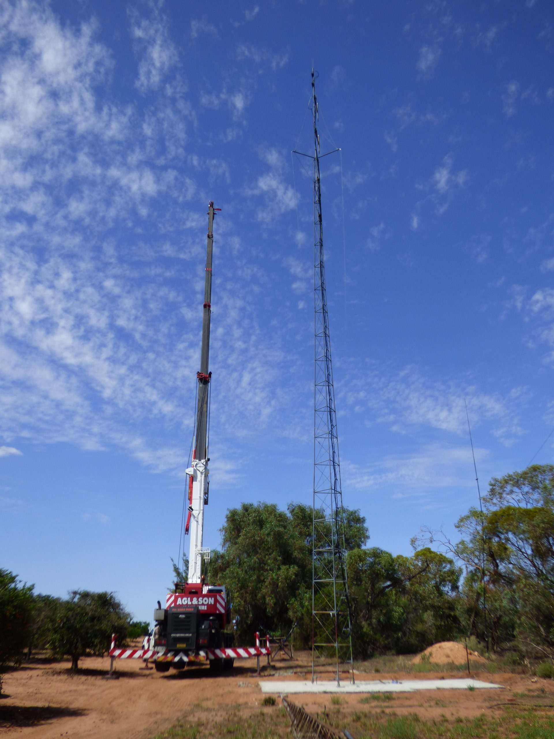
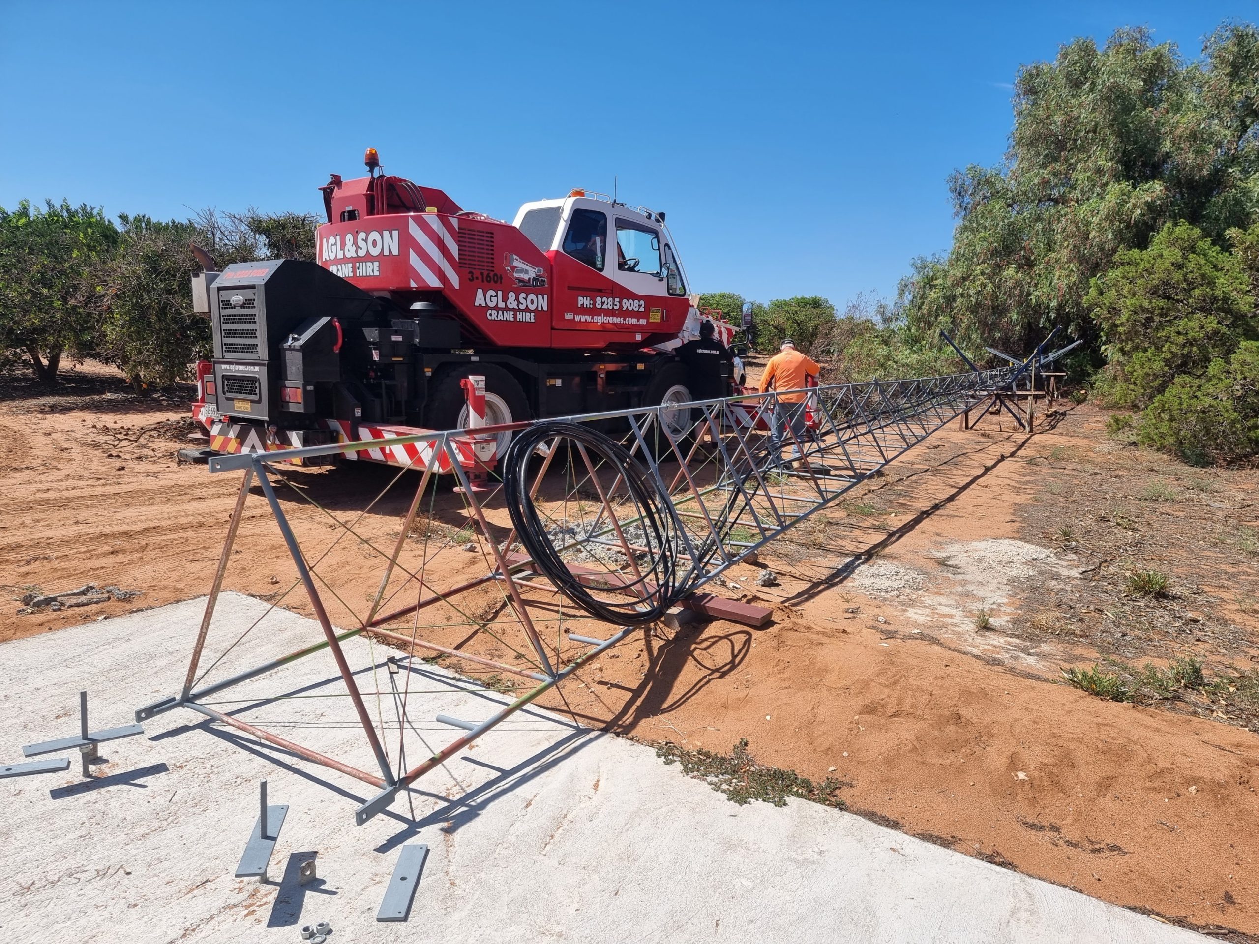 16 Ton Crane setting up.
 Getting ready
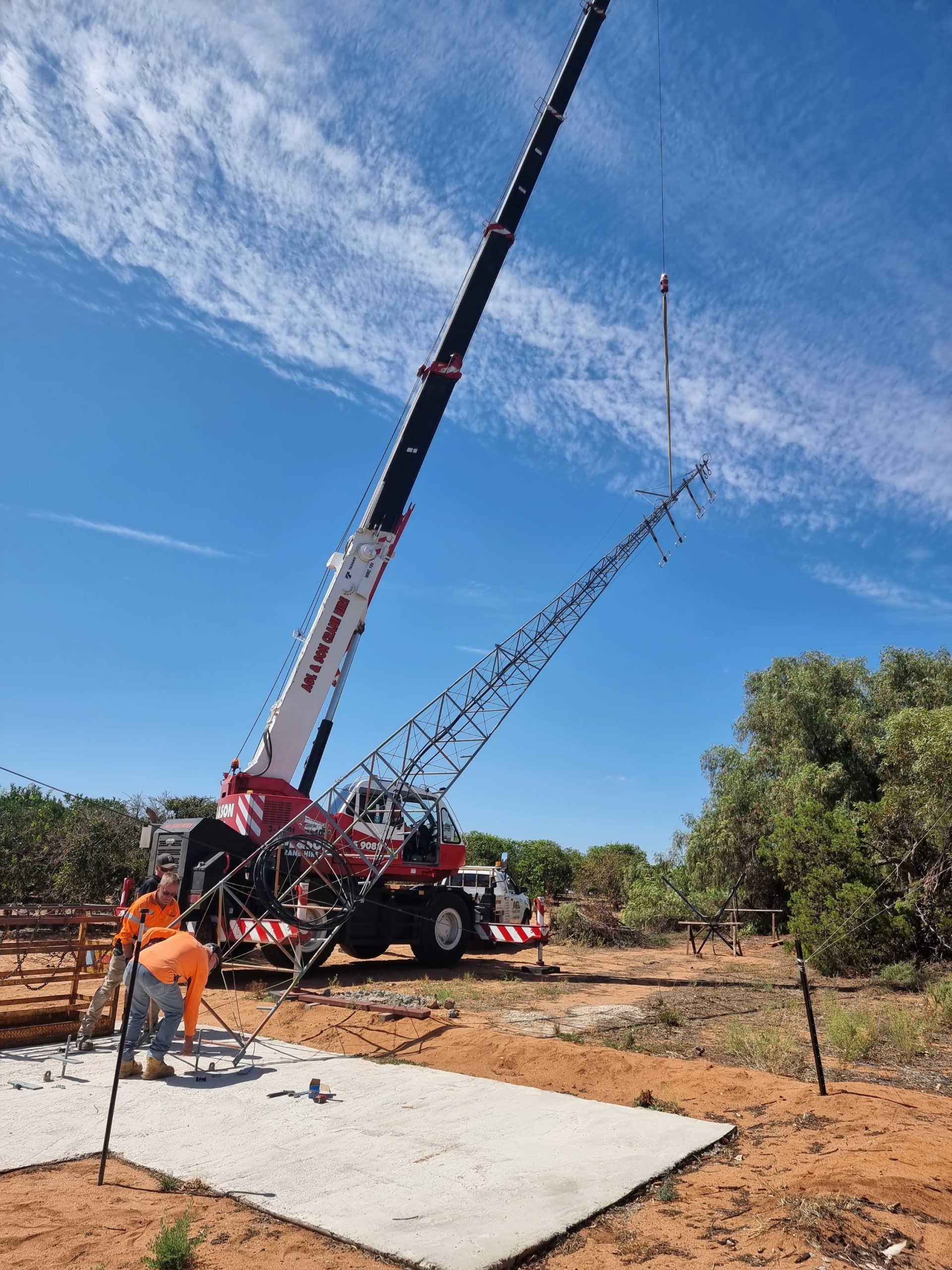 Going up…..
 Going up….
 And up….
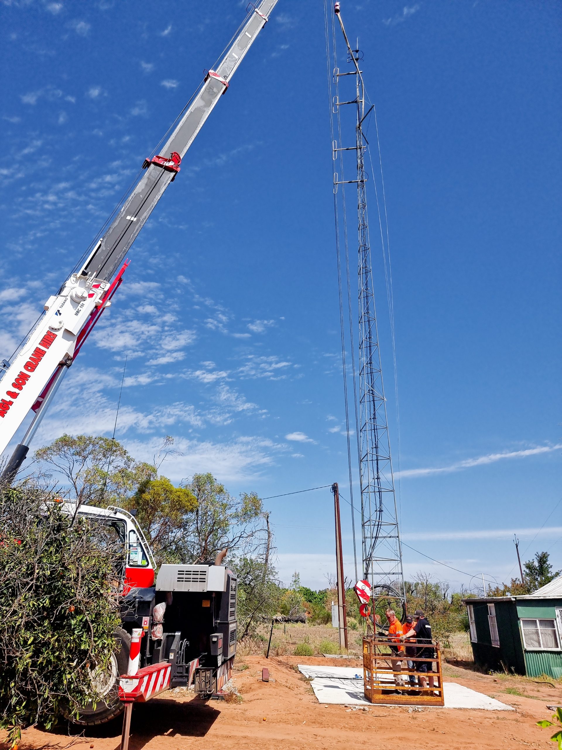
 This tower ain’t going nowhere!
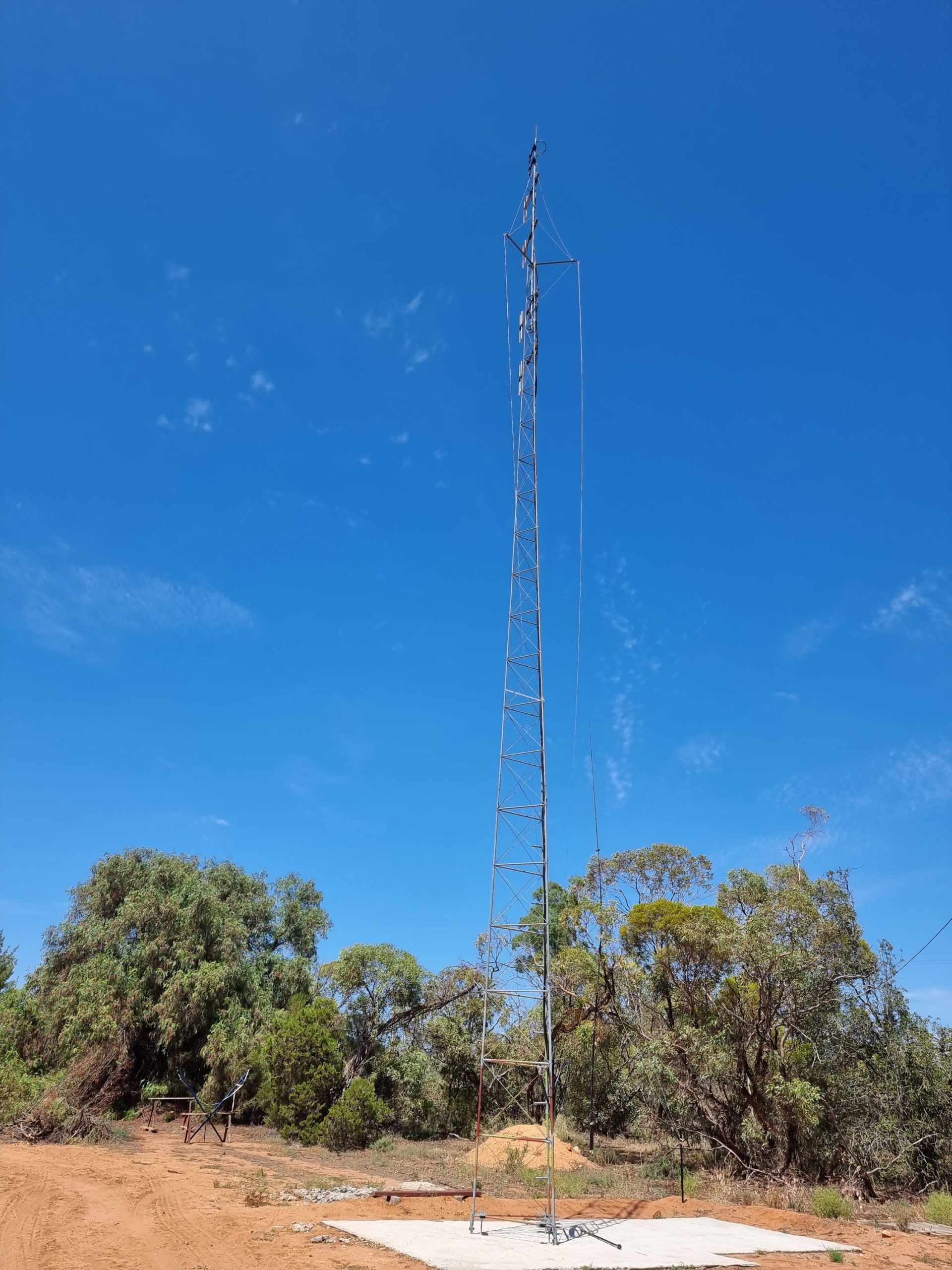 A work of art!
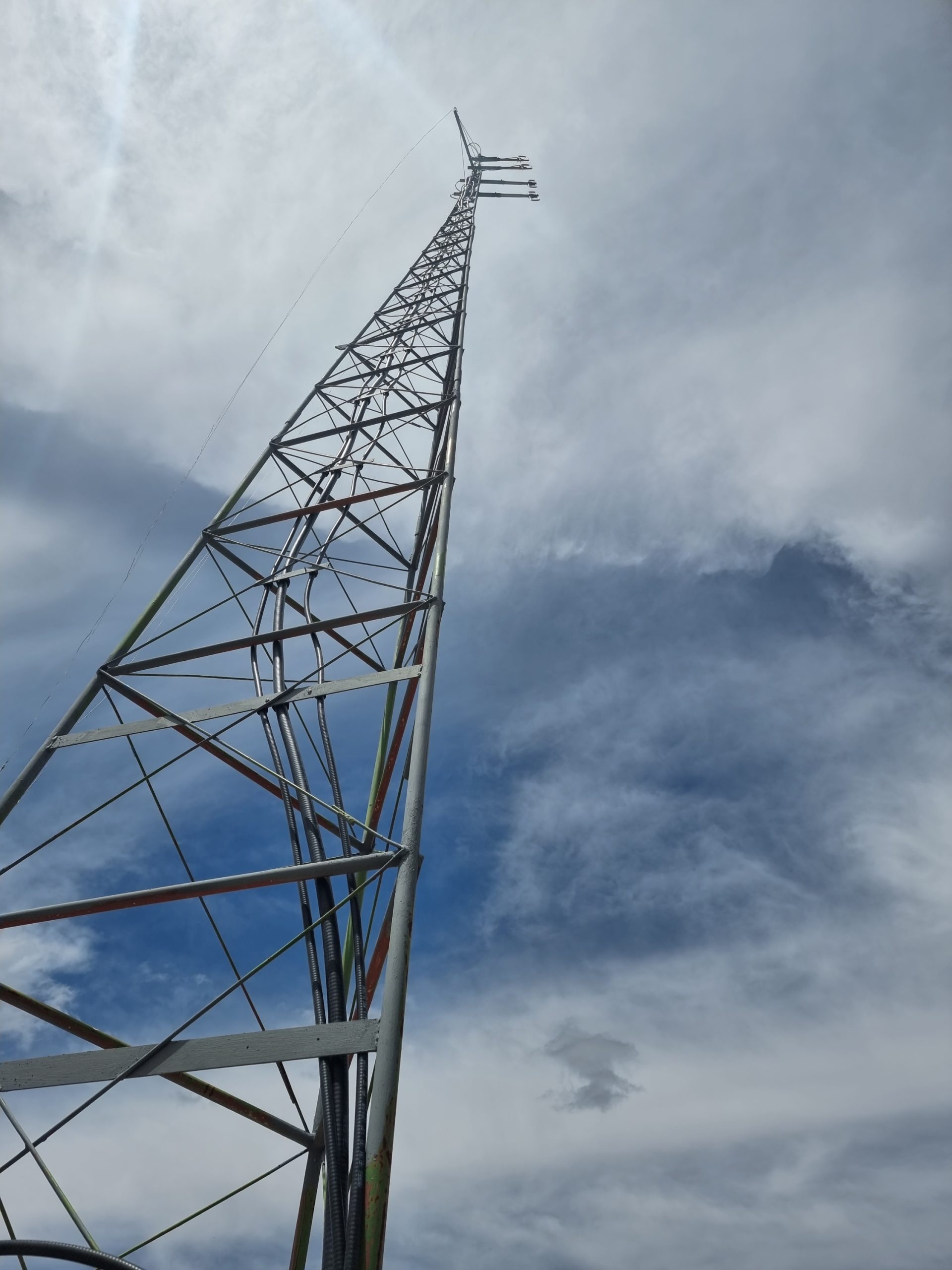 For the astute, yes, some stainless wires run down – sky hooks for low band antenna’s.
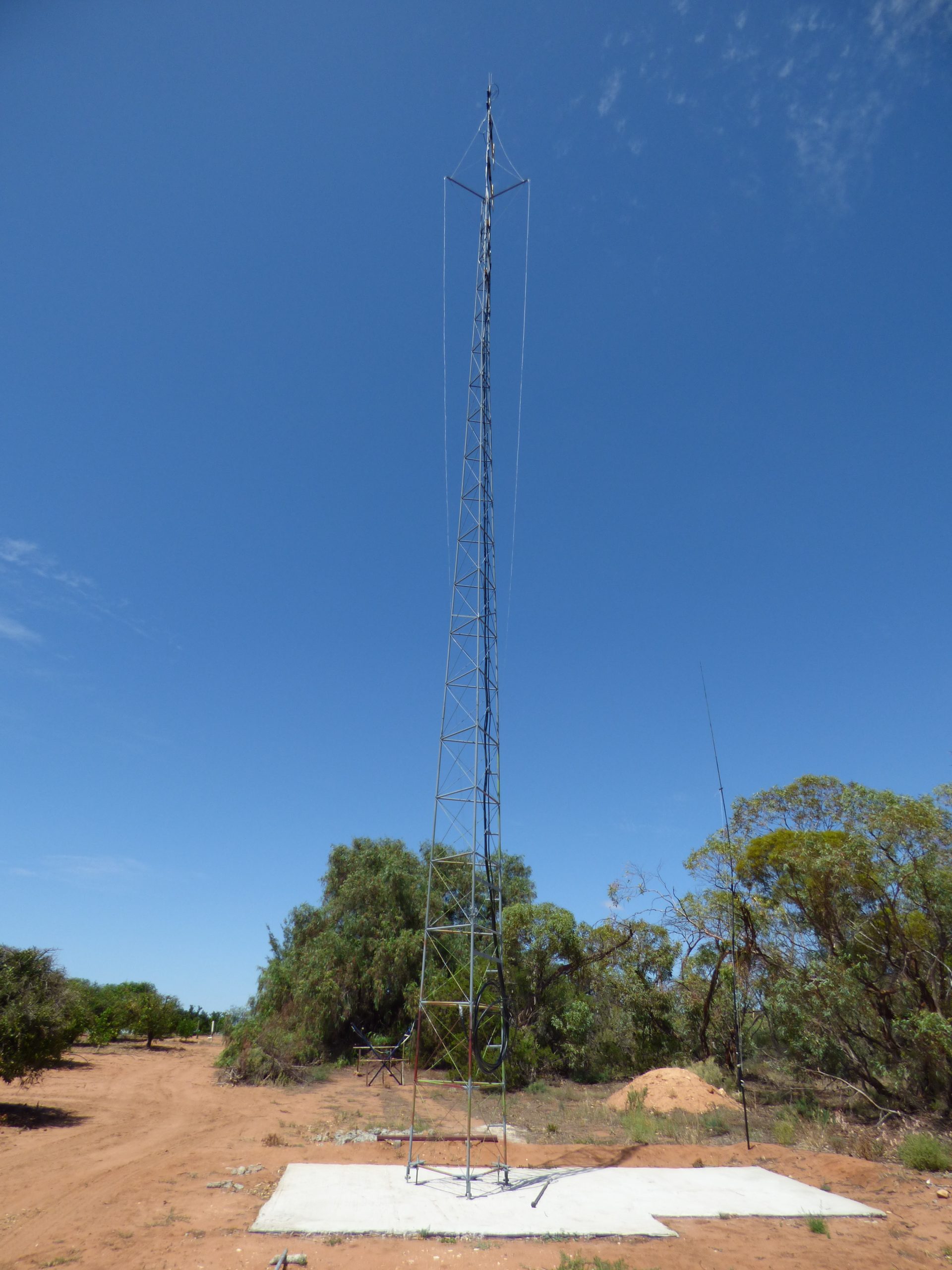
 As a comparison, you can just see the existing VHF/UHF white stick to the right on the corner of the shed. The top of this is about 2M below the lowest VHF (TX) array on the tower, and the UHF array is a full 9.5M higher.
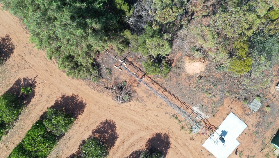
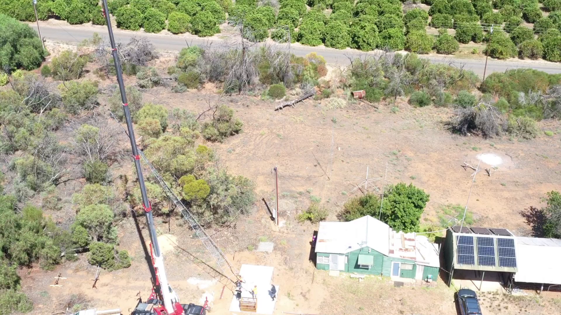
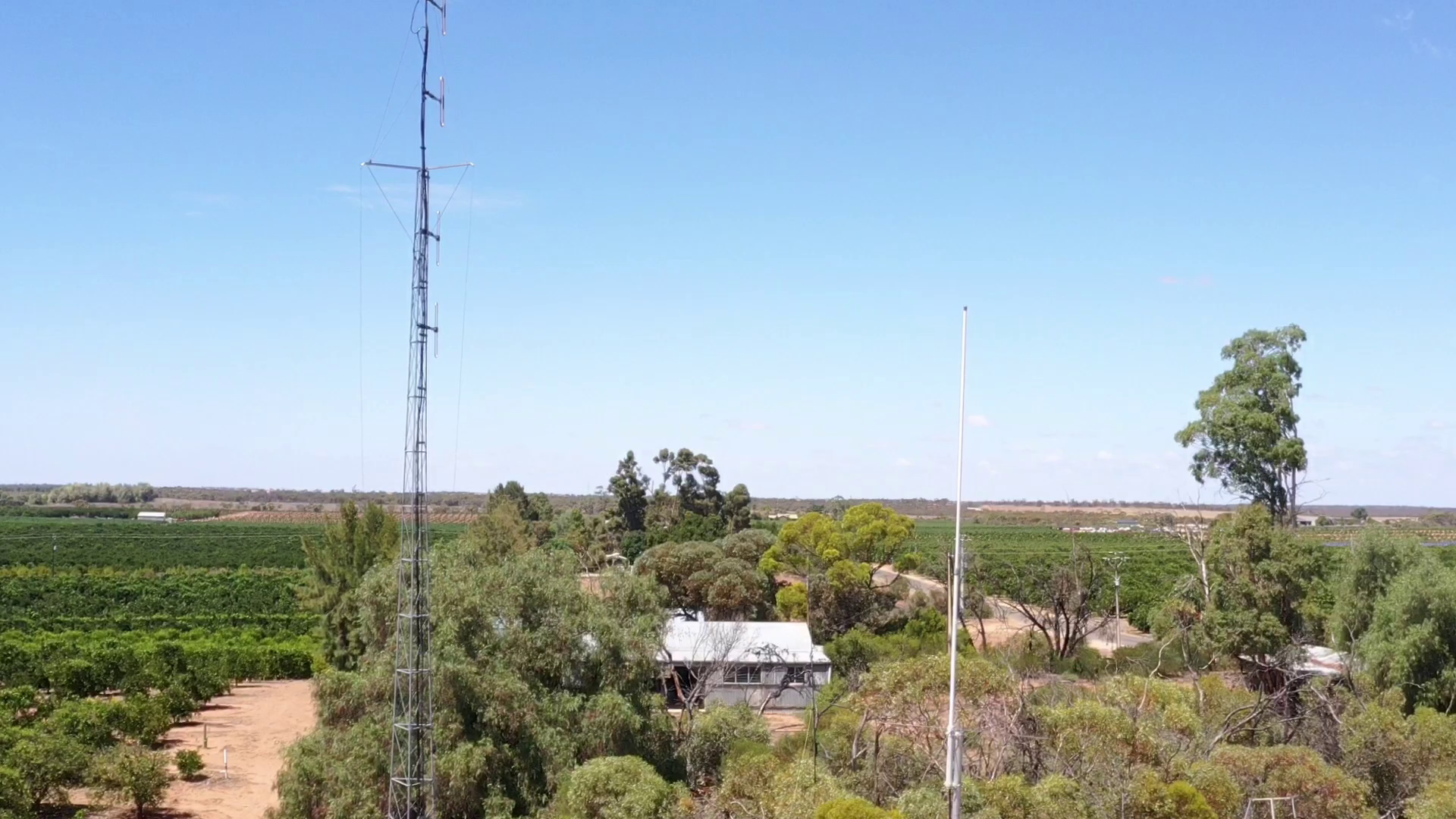 Drone Pic – existing white stick in foreground.
 And, the horizon, this direction it is the range – at Burra just on 100km away.
Next steps are to build the shed beside the tower in the coming weeks.
Update – 27-Feb-22
Shed building time
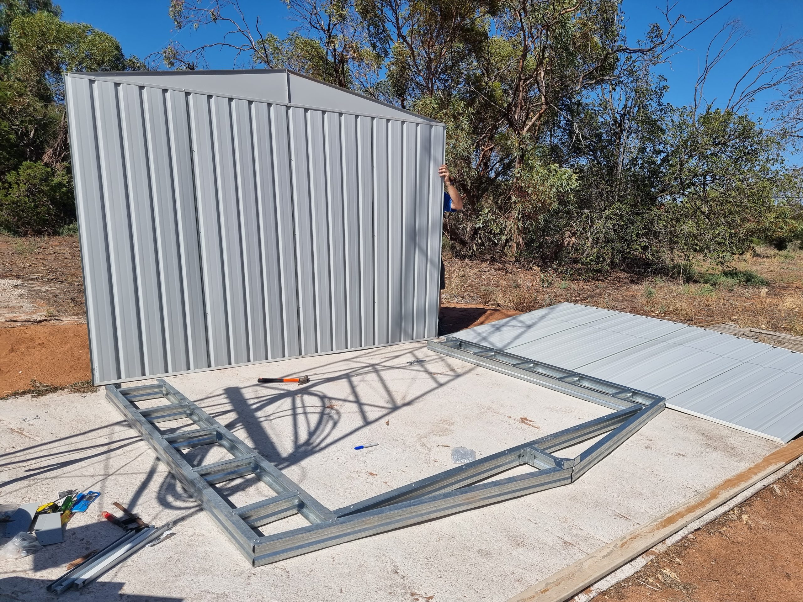
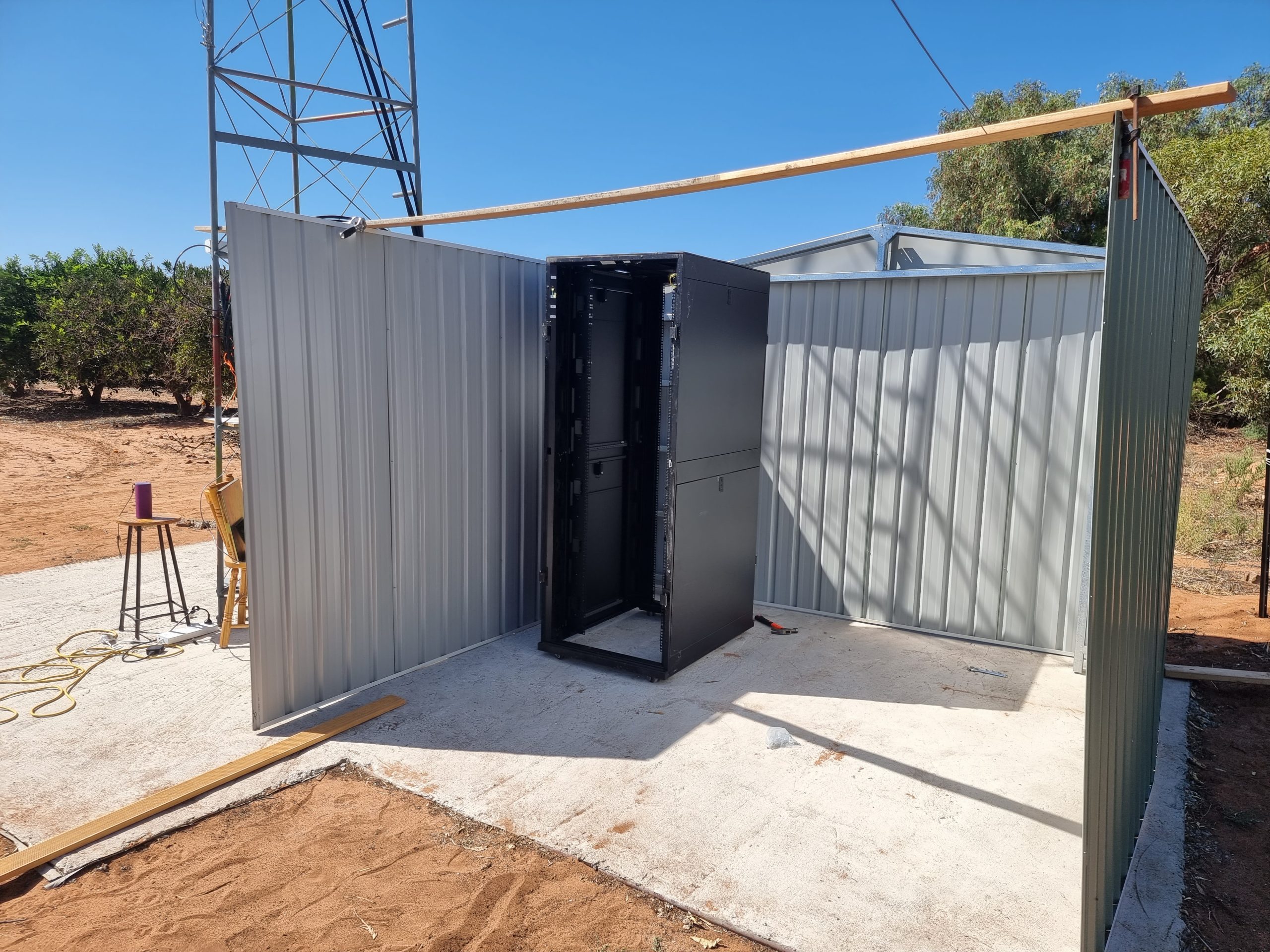
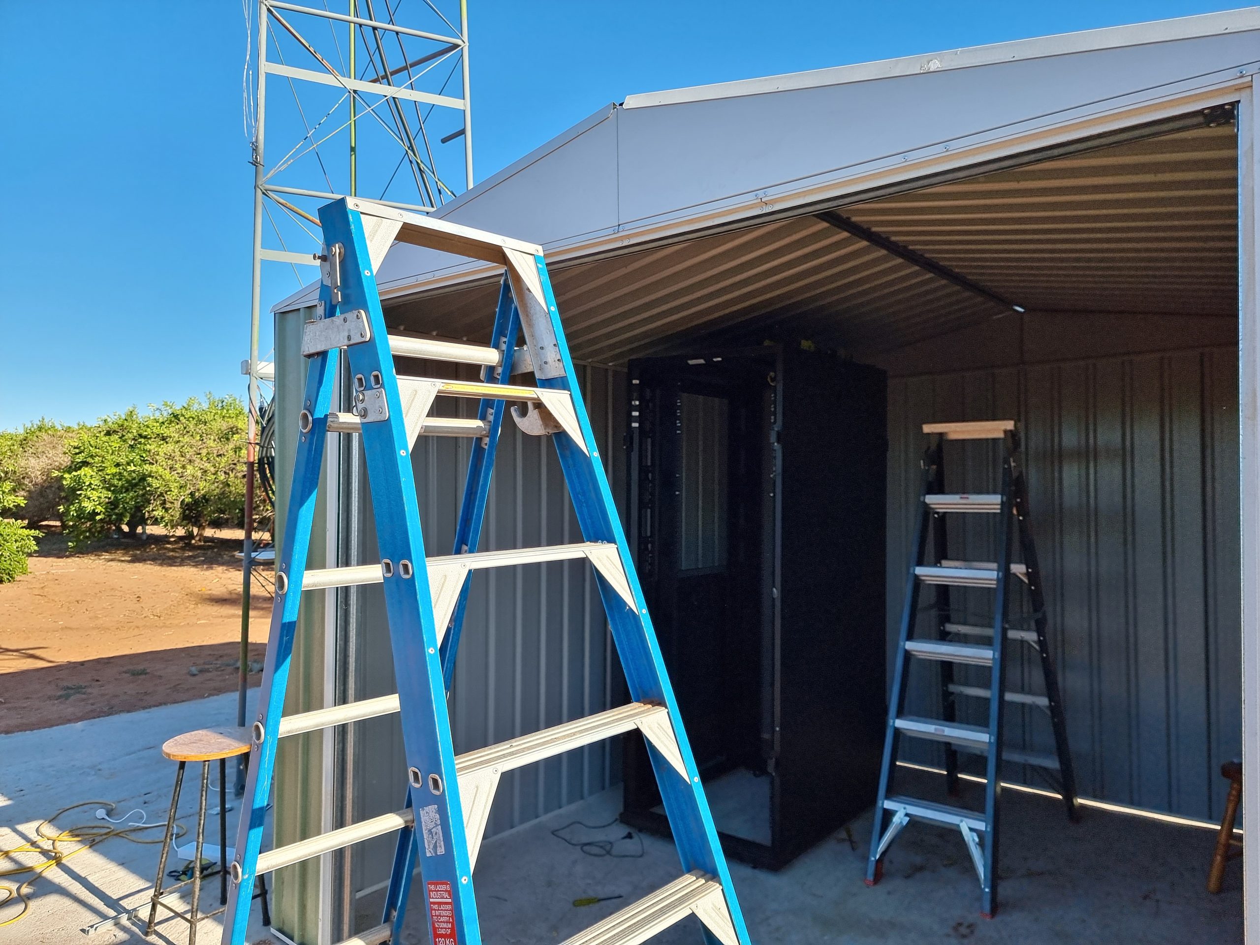
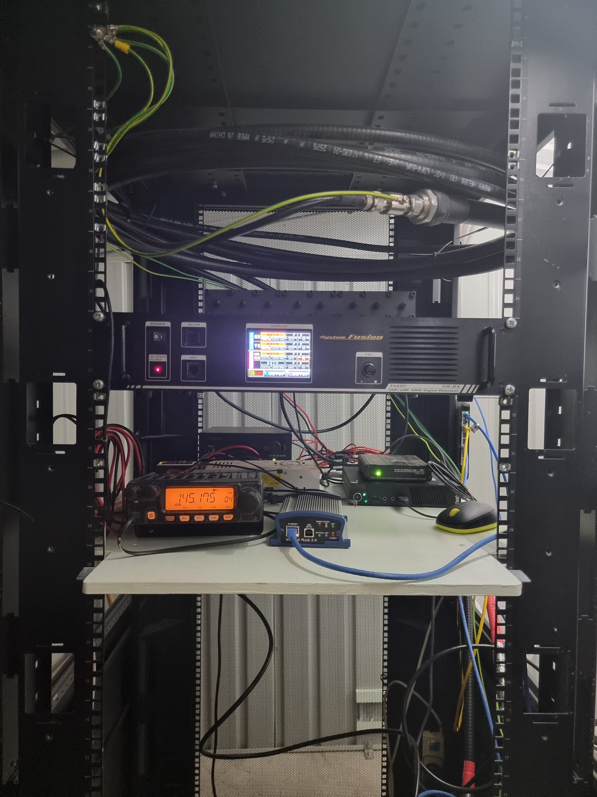
It took a lot longer than expected to build the shed, but once it was completed, it was a matter of bringing in the feeders and installing the UHF repeater into the rack.
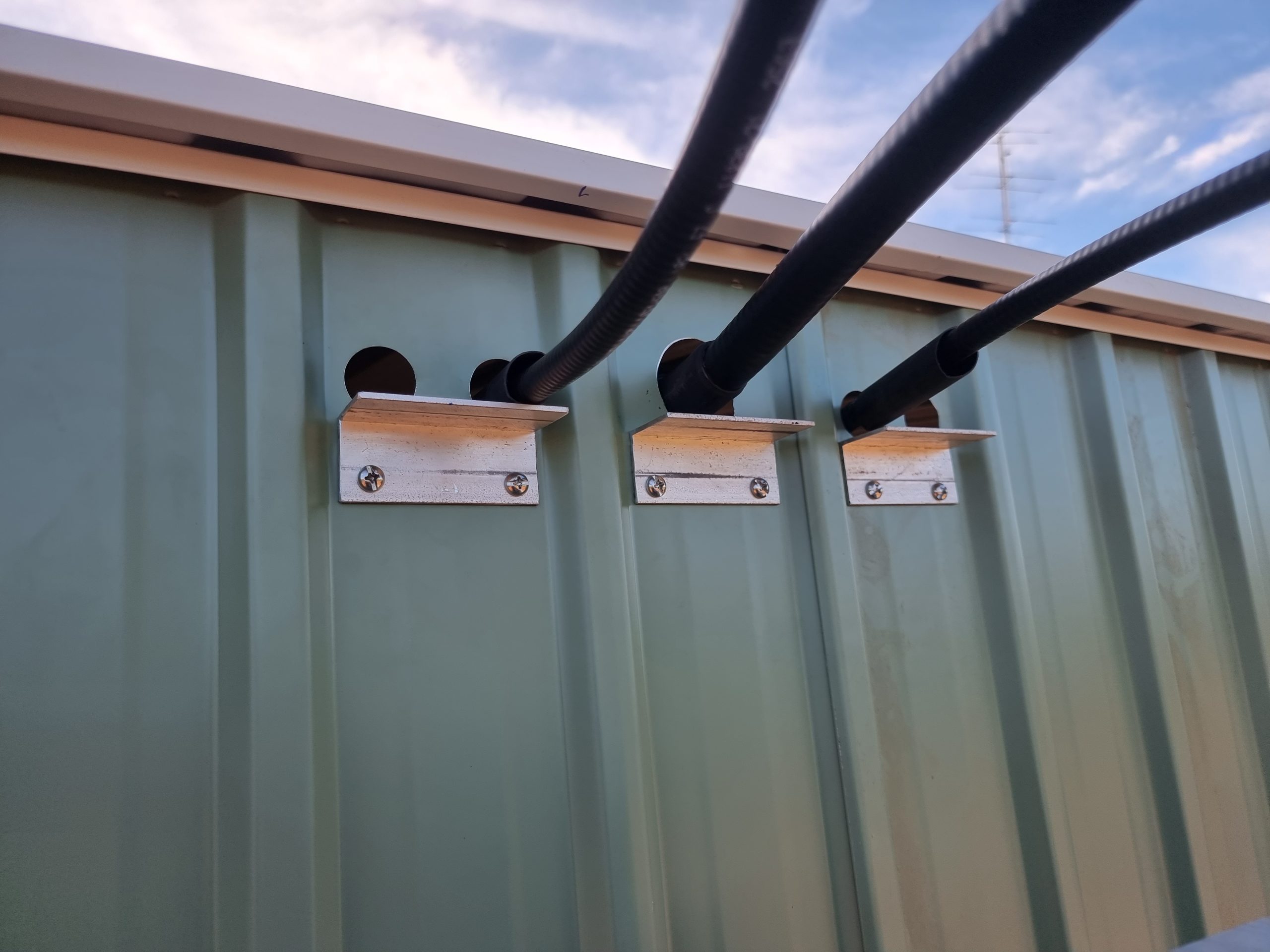
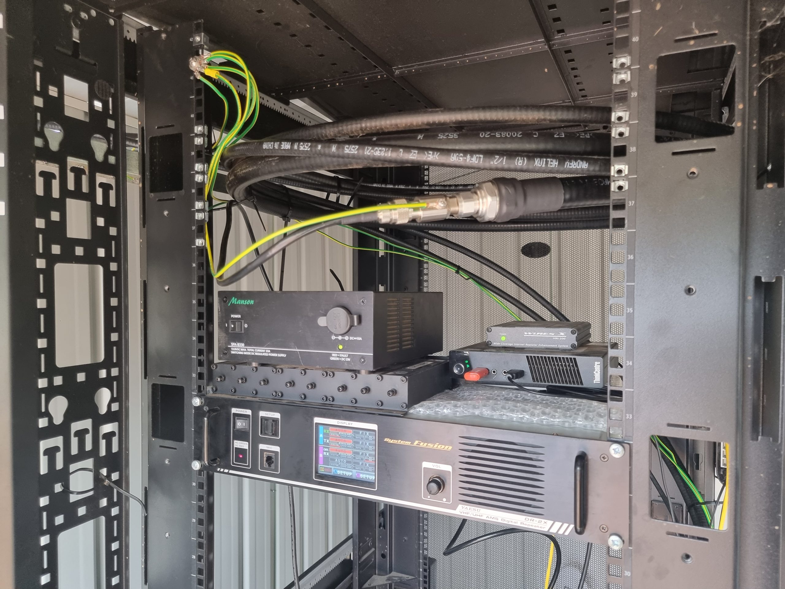
One of the priorities was to EARTH EVERYTHING! and whilst we may not (yet) survive a direct lightning strike, at least we know that we have some protection.
The 2m APRS is currently on the VHF TX antenna and the 30M APRS has also moved.
A short video showing the current status.
Update – 26-Mar-22
It never ends, there is always something more to do on a new site and the next steps were to look at the power.
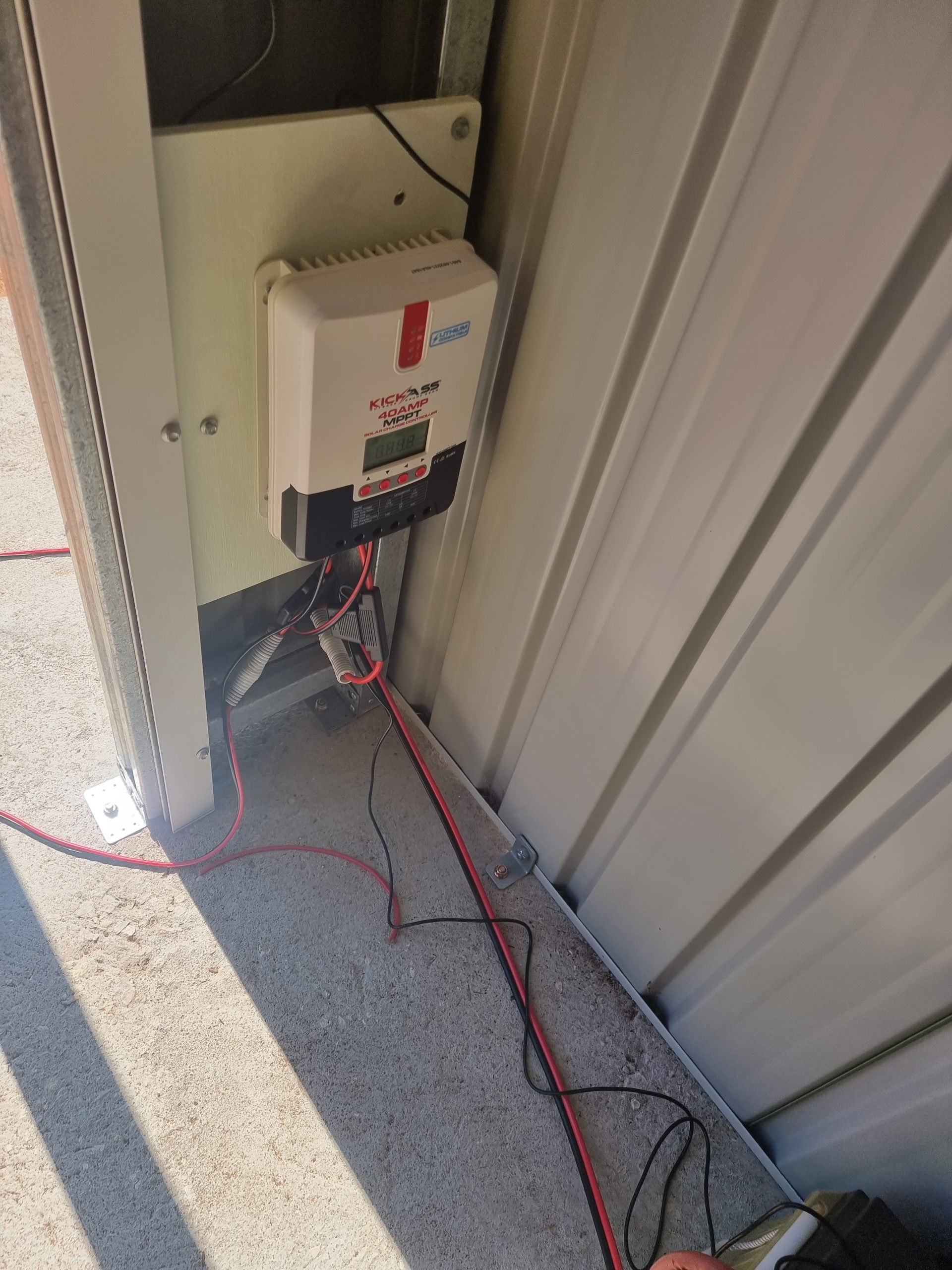
With a pair of 165AH batteries, and 2x250W solar panels, along with a suitable 40A MPPT regulator, and a 20A 240V “backup” supply.
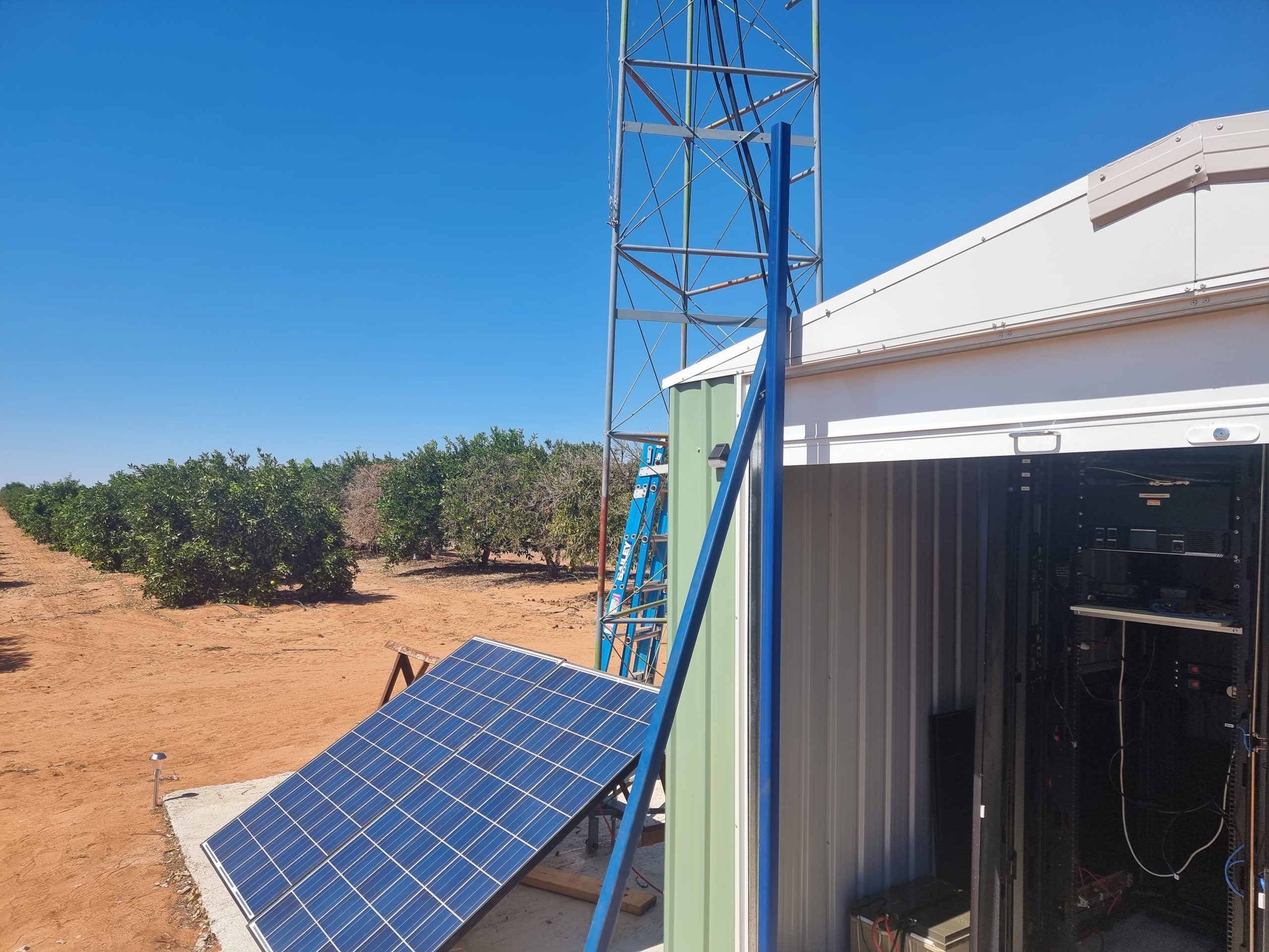
The solar panels will be moved to provide shading over the roof in the coming weeks.

A new set of UHF filters were installed – replacing the notch filters that were in use – which provide much better isolation and front-end protection to the repeater.
Update 10 Apr 22
The solar has already proven to be useful and after a couple of weeks running and everything has settled down it is working just fine.
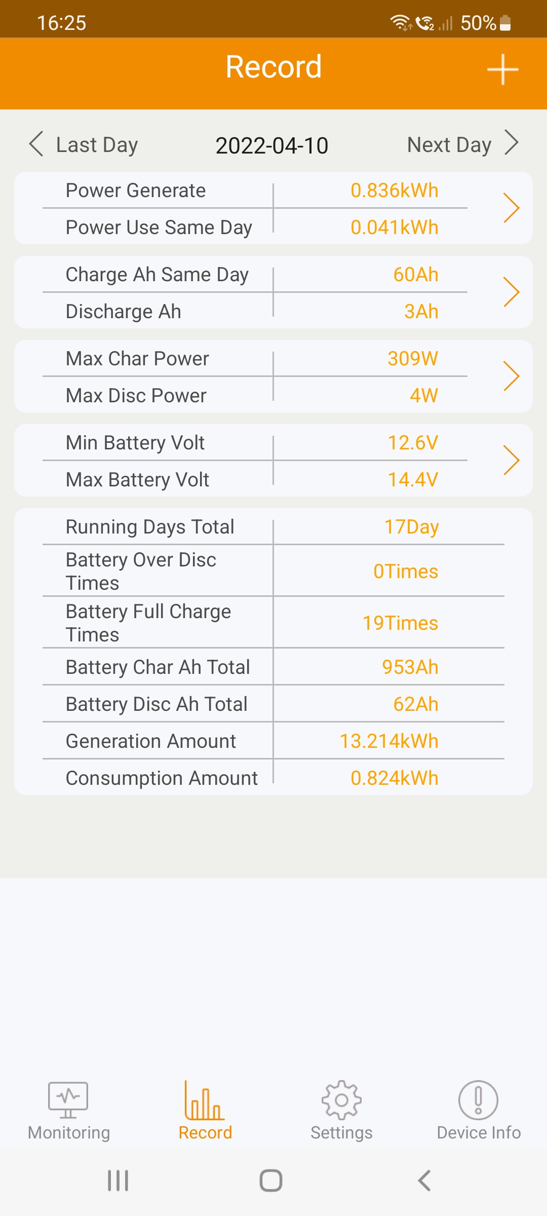
From the App, I can see that after the first few days and the batteries cycled up, that overnight the batteries are not dropping very far, certainly not enough for the backup 240v to kick in.
In preparation for the VHF, an isolation measurement was taken between the 2 vhf antenna arrays, and that was slightly better than expected.
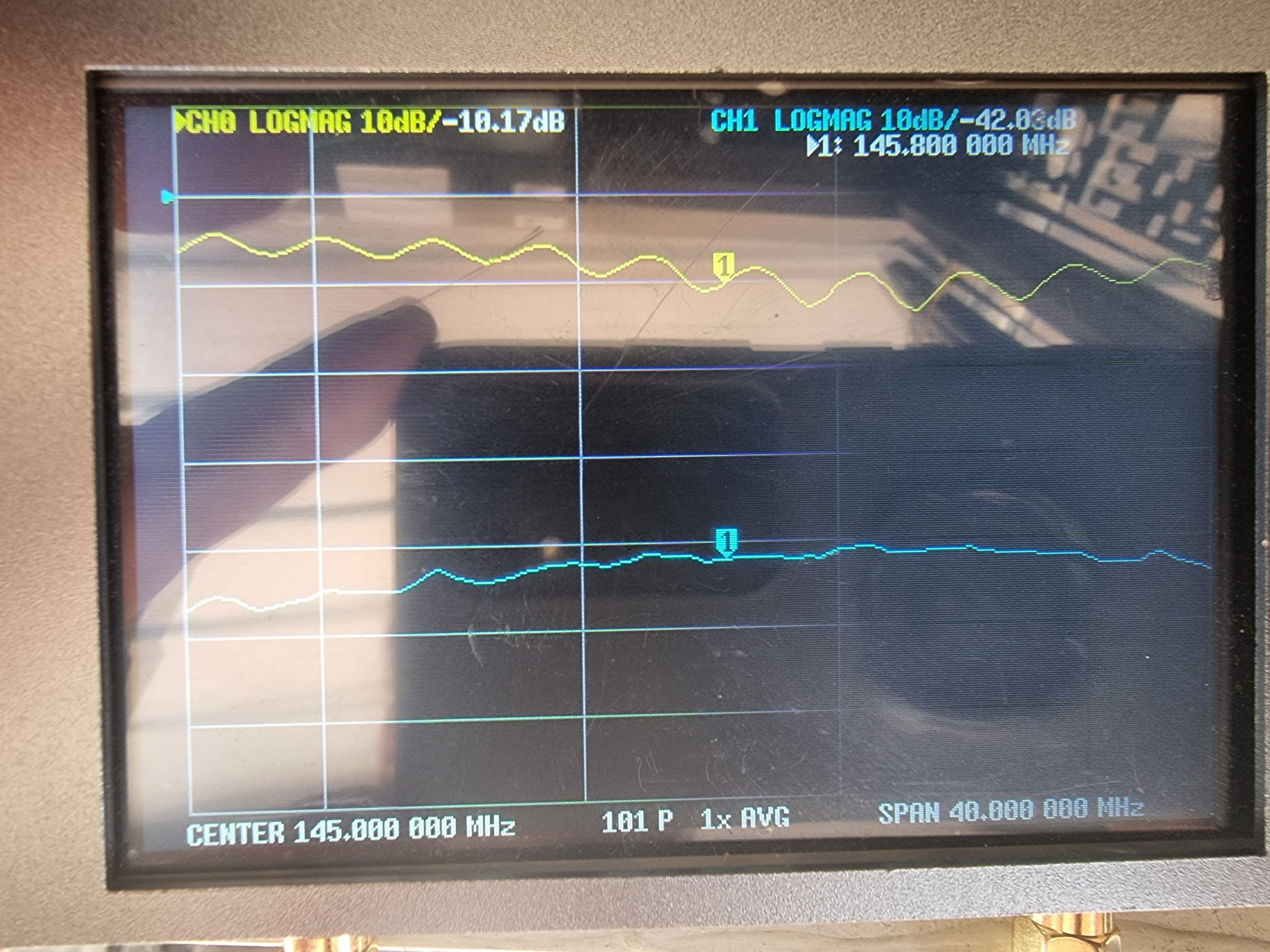
The rx array connected to s.11 port, shows the return loss is not the best, but this was known before the tower went vertical. It does show that the isolation is a tad over 40db which makes the filtering a bit easier!
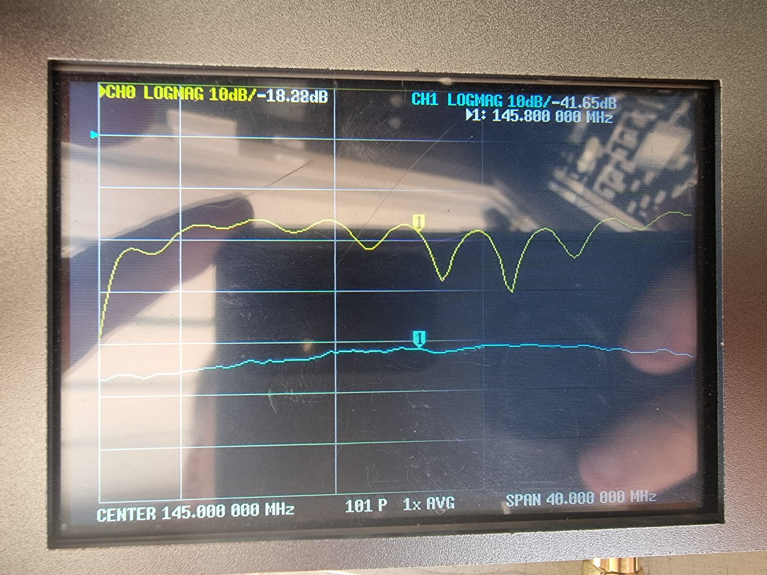 The return on the tx array is much better, and still showing greater than 40db isolation.
Update 5 June 22
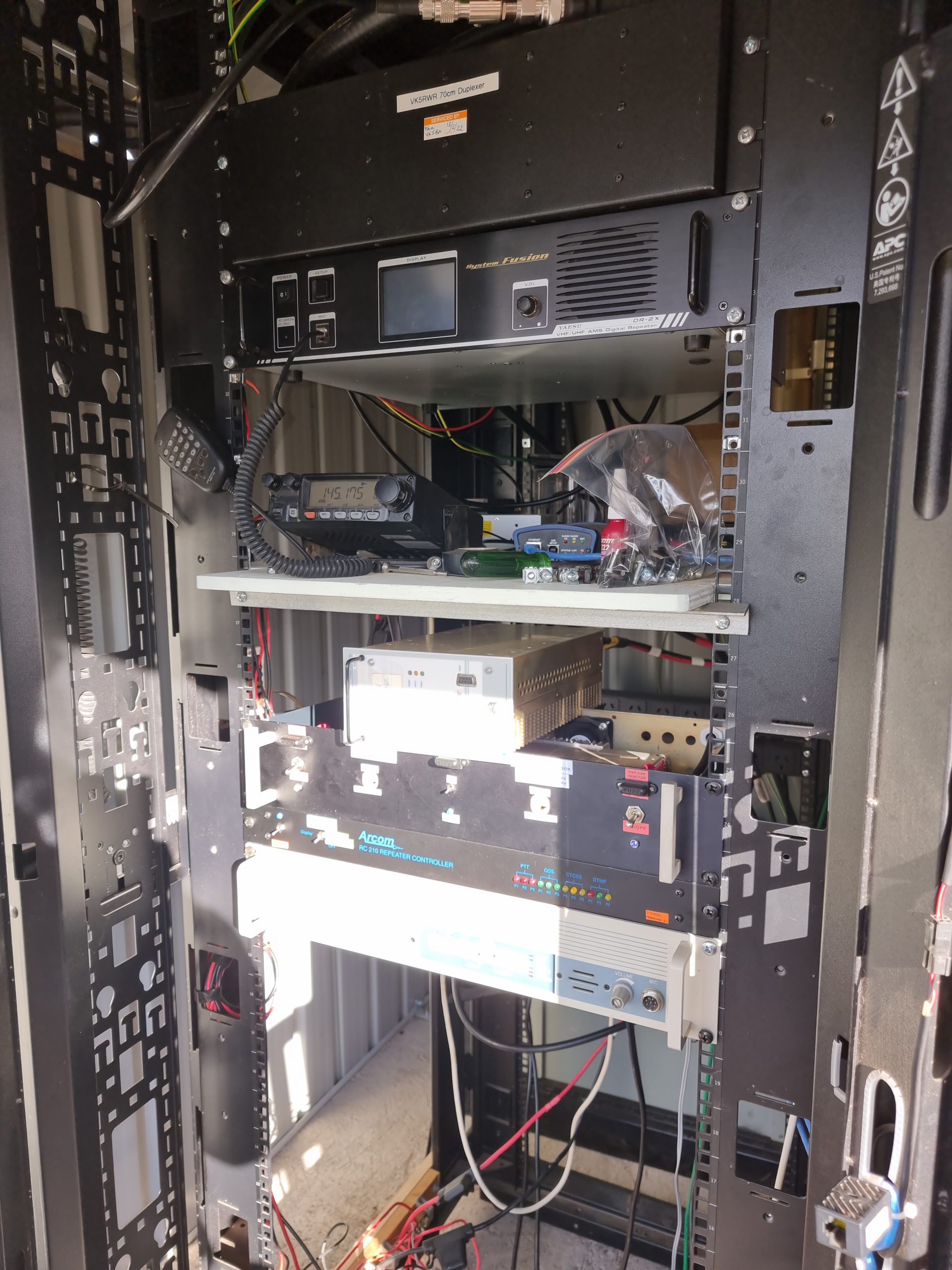
Well after a lot of work, it has finally all come together.
Installation of the VHF repeater, controller, VHF filters and link radio and link antenna.
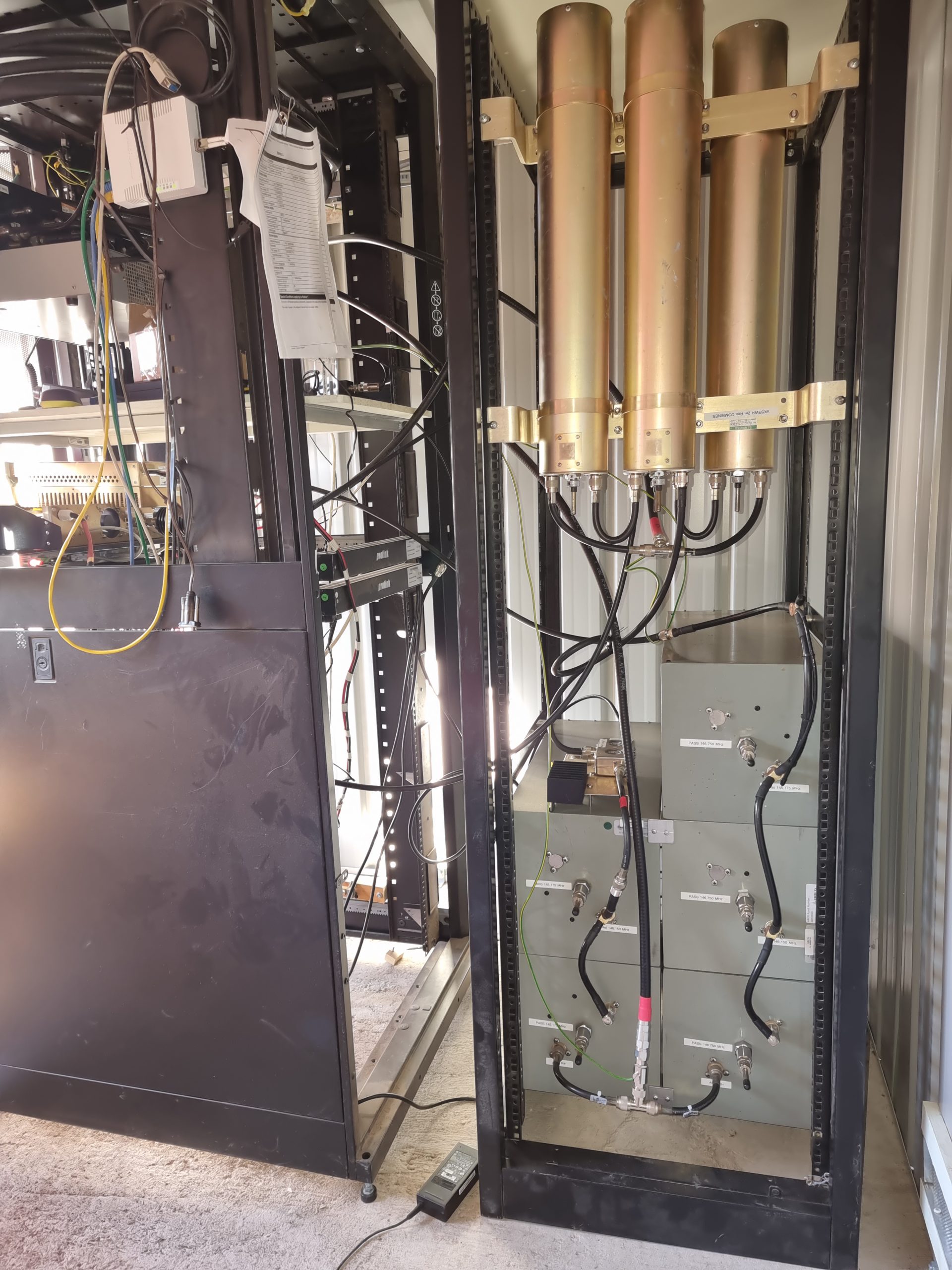
The VHF filters are yes – quite large and at first glance you might ask WTF! – Remember, there is a TX antenna (the big cans at the bottom) and an RX Antenna (the smaller cans in the top)
Big cans, handle the high power and provide great isolation with minimal insertion loss.
The smaller cans, do not need to handle high power, and are therefore tuned with isolation and minimal insertion loss in mind.
Acknowledgements
Along this journey of building a complete greenfield site it could not have happened with the help of a lot of people,
In no particular order, VK5HS, VK5TRM, VK5FR, VK5BB, VK5KX, VK5HMV, VK5NRV, VK5GR and VK5BX and our neighbour Adrian and all the other AREG and Riverland Radio Club members that been of great assistance also