
I recently picked up a 70cm XVTR from http://www.transverters-store.com/432_28mhz.htm – For extra confidence, you can also purchase via their Ebay Store – http://stores.ebay.com.au/tubes-shop
Prices are the same both direct and via Ebay, Ebay for confidence if you are unsure about making a purchase directly from the Ukraine.
It arrived in about 3 weeks, not too bad at this time of the year – I bought the “kit” which includes the completed XVTR, the Attenuator/Interface/Sequencer Board, the case and a selection of connectors to get you all set up ready to use.
You will need a few additional items to put it all together!
There is no layout, nor a complete cabling diagram, you will need to use the individual wiring diagrams of the Attenuator and the XVTR boards to hook everything up. It is quite straight-forward.
The XVTR is a complete no solder board – you just need to wire up the IF input, PTT, 70cm Output and Power to the 2 4-pin headers.
The Attenuator Board, you need to solder the wires as required to interface.
In order to assemble, you are going to require some additional hardware:
5x 12mm M3 Bolts
1x M3 Nut and star/lock washer (for MOSFET)
4x M3 threaded Nylon Stand–off’s 6.5mm*
500mm 18Ga insulated hook-up wire
400mm RG-174/RG-316 coaxial cable
100mm 3mm heat-shrink.
2.2k Resistor (optional)
You should also have the following tools.
Soldering Iron (duh!) – my 15/40W was perfect for the job.
(illuminated magnifying lamp – optional but makes things easy)
Screwdriver #1 philips
Drills – 3.3mm (M3 clearance)
Drills – 5mm, 6mm, 8mm,
Round file/Dremel.
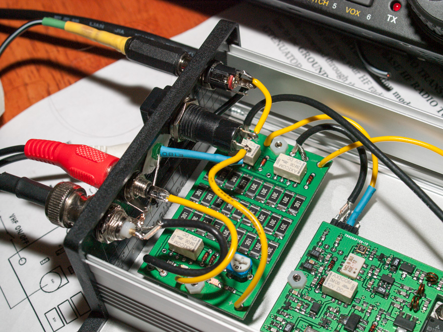
First off, I selected a physical placement of the XVTR and the Attenuator boards such that:
- The 432 output cable could be as short as possible
- The output MOSFET was positioned such that it had maximum amount of the case near it – as per the instruction sheet
I chose to use a different switch than the supplied one, I chose a push-on push-off switch rather than the toggle, because it was a smaller hole to drill in the case for mounting.
There was nothing in the way to indicate any sort of layout of the required connections, so, it really was simply making a sensible choice while keeping all leads as short as possible. I just picked a layout that would allow a little bit of cable to enable assembly without any cable stresses during assembly.
Mark out and drill the mounting holes in the case for the 2 boards.
First off, you will need to cut 1 of the M3 nylon mounts such that it will support the XVTR board with the MOSFET mounted directly to the case.
Once done, mount the XVTR board – noting that the mounting holes are correct size to thread the M3 bolts thru – no nuts required – and significantly, the mounting hole near the output end, no nut would fit as the air-wound coil is too close!
I used a cut-off piece of the threaded M3 mounting post as the Nut for the other end of the board.
Next step was to prepare the Coaxial cables (3x) and Power (in and out) and PTT (in and out) and solder to the Attenuator board.
Next, mount the board to the case and put aside.
The ends of the case are plastic and therefore easy to drill and install the connectors and the power LED.
I used a sticky label on the inside to mark out the position of all the connections and then proceeded to drill/file (as needed) to fit the connectors to the Input end:
I positioned the connectors to align across the top of the end panel so that there would be no interference with the mounted board and still allow a sensible layout of the leads.
The layout I chose was L-R: Power (6mm hole), Power Switch (12mm hole), Power LED (5mm hole), PTT (6mm hole) and the 28Mhz IF in/out BNC (8mm/shaped hole)
I mounted all the connectors, and a little quirk indicated that the only GND input to the Attenuator board is via the Input Coax, so on the switches, I tied the GND connectors from the power, RCA(PTT) and BNC (IF in/out) together across the back of the connectors on the panel.
Once done, then I secured the end panel to the bottom of the case and hooked up all the connections.
I wired up the LED I put on the panel (with the 2.2K R) to the switch output with a bit of the heat-shrink over the lead and resistor, and the other end to the common earth bus. At this point, I applied power to verify everything.
I did note that the attenuator board does in fact have a power LED and an PTT LED on it – which is good for checking while it is all apart, but you will not see once the cover goes on!
From here, I now wired up the 2x 4-pin header connections from the Attenuator to the XVTR board. As I was dealing with power and PTT close to either an RF input or output, I opted to put a bit of heat-shrink over the soldered connection to the header pin to ensure I didn’t short out anything.
Next step was to to then mark out the 2 BNC connectors on the other end – the HF-passthru and the 70cm ports and mount them to the end.
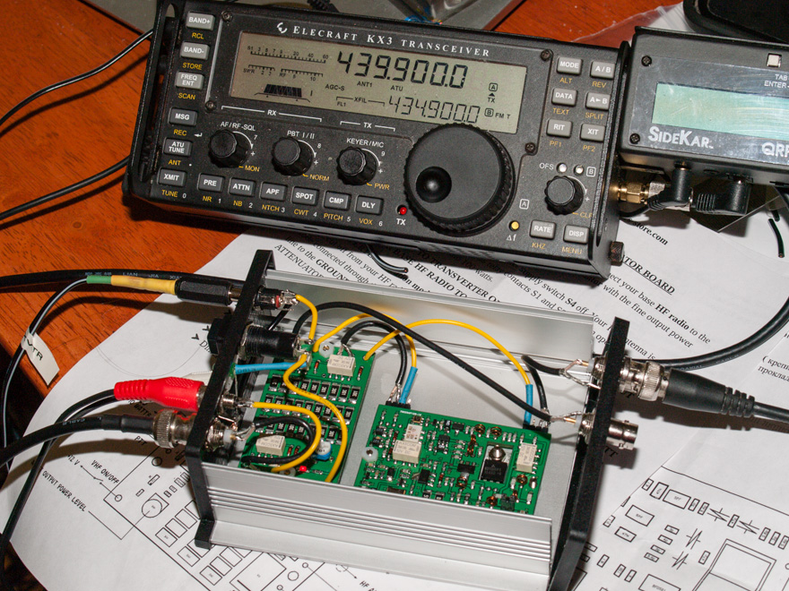
Finally, everything wired up, and hooked it all up with the KX3 configured as the IF, attached an antenna.
With a drive requirement of 1-10mW and the 30dB attenuator, I set the KX3 IF Max output to 7W (7mW after the 30dB atten). The Attenuator has 30dB in front of the variable – and I wanted to set the pot for no extra attenuation of the input.
Knowing I was in safe territory and would not exceed the 10mW Max IF input to the XVTR, I then set about setting up the atten drive. I set the KX3 to output 2W (or 2mW) and then using a nearby Handheld without an antenna on it, adjusted the pot for Maximum RX signal.
At this point, it was ready for a couple of final photos and close up the case – nothing more to do in there.
Once closed up a couple of simple on-air tests were conducted with a nearby station (Thanks Ray – going mobile about 3km away!) where we conducted a series of tests.
First off, a quick test on FM, and It delivered a similar result to the handheld running at 2-3W output.
Next, it was a quick test on SSB. It took a little bit of effort here, as at first it was around 1.3Khz high in frequency. After a few minutes of talking, the bottom of the XVTR was a bit warm, but not excessively so, I needed to adjust things a little and found that it was around 480hz high in frequency. So, it seems that there is some temperature related drift.
It did not seem to drift any more after the initial 3-5 minutes of use and warm-up, but time will tell.
I will of course note the offset and map it out and apply the required offset within the KX3 XVTR configuration so the display reads correctly.
For the cost, this is a great little afternoon project of mostly a mechanical build that will give you 70cm capabilities in an ultra-small, lightweight package.
Now, I just need to get out there and experiment with it somewhat to determine the real-world sensitivity and actually measure and plot the output power with various input power settings.
Finally a short video accessing the local repeater.
I’m looking at getting a KX3 (to replace my KX1 and to use on a big hike I have planned at the end of June where I would benefit from a higher performance rig than the KX1 but don’t want to lug the weight of my K2 along for 50+ miles of hiking). I have some transverters that I was thinking of selling, but after reading your post, maybe I don’t want to do so now.
How do you get the correct frequency to display on the KX3? Do you define another “band” with a frequency offset as per the transverter? If so, how many can you do with that, just one or multiple ones?
Cheers!
Mark – The KX3 can be configured to use a 28 or 50Mhz IF and you can enter the offset directly and have up to 9 transverters configured to display the correct output frequency on all bands right up to 24Ghz. The only drawback is the 2M module is in fact an Internal Transverter. So if you need a 144-148 IF, then you do not get the direct display on the KX3